

 EN
EN  English
 русский
 Español
 عربى
عربى

News
 Home / News / Industry news / What Is the Torque of a Slewing Bearing? Friction, Formulas, and Selection Guide
 What Is the Torque of a Slewing Bearing? Friction, Formulas, and Selection Guide
 2026.08.28
 Industry news
When a crane's upper structure hesitates on its first swing of a cold morning, the problem is rarely the motor alone. Far more often, nobody sized the drive for the torque hiding inside the bearing itself. The torque of a slewing bearing is not a fixed figure printed next to the load ratings on a datasheet. It is the resistance the bearing creates against rotation: friction from rolling elements carrying the load, from seal lips riding along the ring, and from gear teeth where an integral gear is fitted. The short answer is this: a slewing bearing's torque is a variable friction load, commonly 1.5 to 2 times higher at breakaway than during steady running, and it belongs at the center of drive sizing, not at the margins.
Content
- 1 Three Different "Torques" Get Confused in Slewing Applications
- 2 The Three Components of a Slewing Bearing's Friction Torque
- 3 How to Calculate Slewing Bearing Torque
- 4 Starting Torque Versus Running Torque
- 5 What Pushes Slewing Bearing Torque Up or Down
- 6 What to Confirm With Your Supplier Before Ordering
Three Different "Torques" Get Confused in Slewing Applications
Before calculating anything, separate the three quantities that engineers casually call "slewing torque," because a value for one of them tells you almost nothing about the others.
- Bearing friction torque — the resistance generated inside the bearing itself by rolling elements, seals and gears. This is what the term usually means.
- Required drive torque — everything the motor or pinion must deliver: bearing friction plus inertia during acceleration plus working resistance such as wind load or digging reaction.
- Holding or braking torque — the static torque a drive can resist without damage. This is a drive specification, not a bearing one.
A slewing bearing datasheet rarely quotes a single friction torque number, and that omission is deliberate. Friction depends on the axial load, radial load and tilting moment you actually apply, on the clearance or preload class you order, on lubricant viscosity and on temperature. Two identical rings can differ by a factor of three in measured resistance depending on duty, so treating it as a constant is where most selection mistakes begin.
The Three Components of a Slewing Bearing's Friction Torque
Manufacturers model total friction torque as the sum of three parts: M = Mf + Ms + Mg. Each behaves differently in service, which is why the split matters.
Load-Carrying Friction Torque (Mf)
Rolling resistance is generated where balls or rollers meet the raceways under the applied axial load, radial load and tilting moment. It grows with load, steeply so under large moment loads that press one side of the raceway hard into contact. Ball designs show point contact and generally lower resistance; roller designs carry more load per size at the price of higher friction when fully loaded.
Seal Friction Torque (Ms)
Seal lips sliding on the ring surface produce a drag that is nearly independent of load. On a small or lightly loaded bearing, seals can account for the majority of total friction, and every additional lip adds to it. Two bearings with identical envelopes but different seal arrangements can therefore demand noticeably different drives.
Gear Mesh Friction (Mg)
Geared rings add friction at the pinion and ring interface, influenced by gear quality grade, module, lubrication and mesh alignment. On externally geared units, a misaligned pinion shows up as both elevated torque and localized tooth wear.
| Component | Symbol | Source of Resistance | Behavior in Service |
|---|---|---|---|
| Load-carrying friction | Mf | Rolling contact under axial load, radial load and tilting moment | Rises with load; dominates on heavily loaded rings |
| Seal friction | Ms | Seal lips sliding on the ring surface and grease shearing | Nearly constant; dominates on small or lightly loaded bearings |
| Gear mesh friction | Mg | Pinion engagement with an external or internal gear | Present only on geared rings; grows with misalignment |
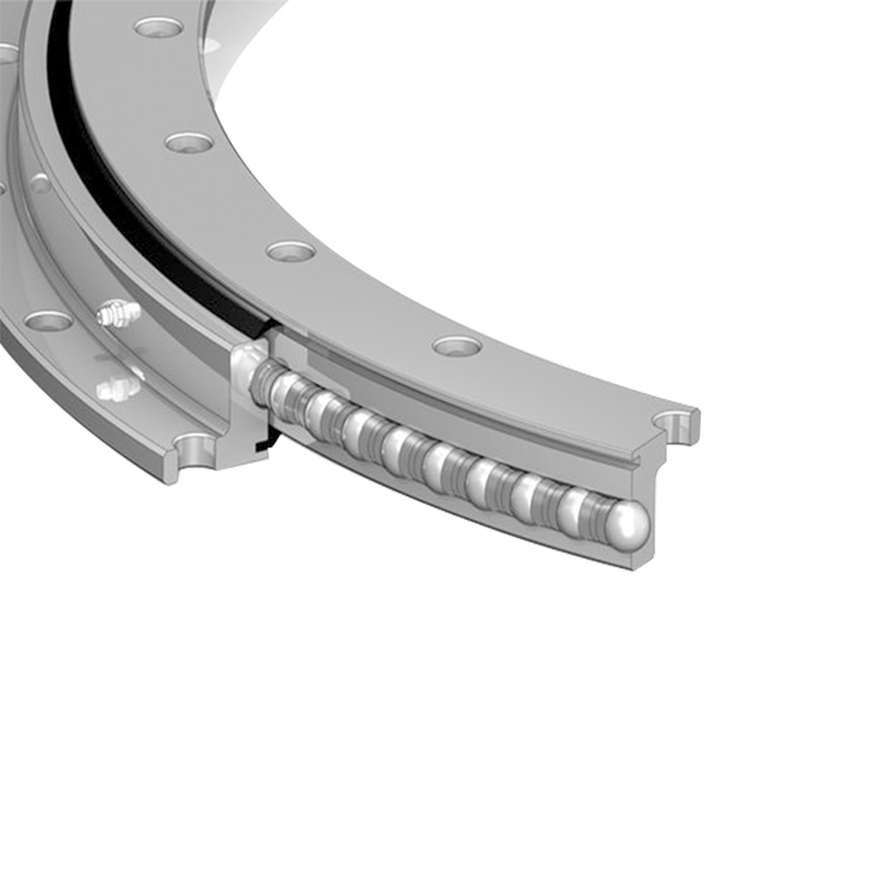
Because these components scale differently with size and duty, structure choice shapes the torque budget. In light and medium-duty equipment such as solar trackers, small positioners and food machinery, a single-row ball slewing bearing keeps rolling and seal friction low enough that compact, low-power drives remain viable.
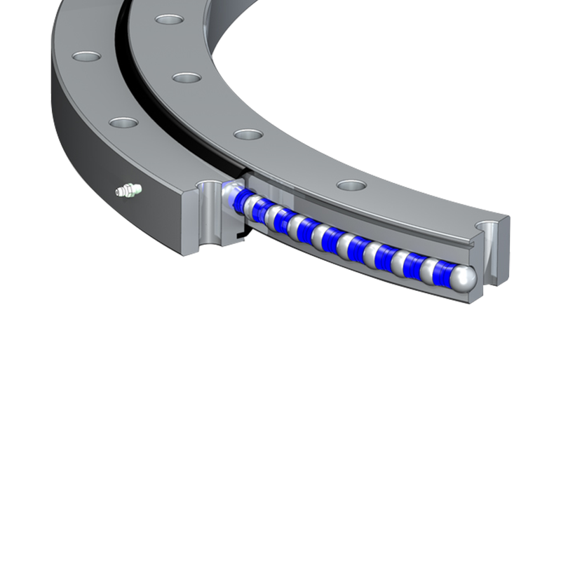 Single-Row Ball Slewing Bearing for Light-Duty RotationWith one row of hardened steel balls, this bearing keeps rolling and seal friction low, so compact drives in solar trackers, small positioners and food machinery stay viable. Heat-treated raceways, sealing options and easy installation support long, stable service.View Product →
How to Calculate Slewing Bearing Torque
Serious projects work the numbers from both directions.
From Available Power
The practical drive-side formula is M = P / ω, where P is power delivered at the ring and ω is angular velocity in radians per second. A platform slewing at 1 rpm turns at ω = 2π/60 ≈ 0.105 rad/s. If 1.5 kW reaches the ring at that speed, the available torque is about 1,500 / 0.105 ≈ 14,300 N·m, roughly 14 kNm. Run the arithmetic in reverse to check whether a proposed motor and gearbox can actually deliver what the application demands at real slewing speeds.
From Friction
A first-pass estimate multiplies the equivalent contact load by the raceway radius and a combined friction coefficient: M ≈ µ × F × d/2. Working values of µ between roughly 0.005 and 0.015 cover rolling contact plus seals, with the low end for lightly preloaded ball designs in warm, well-lubricated conditions and the high end for heavily loaded or cold-running units. Manufacturer formulas refine this into polynomials that weigh the axial, radial and moment terms separately, so use them for the final check rather than the estimate.
Adding the Rest of the Duty
Total demand is M_drive = M_friction + M_inertia + M_working. Inertia torque dominates on fast-indexing automation and tracking systems; working resistance dominates on excavators and cranes. Where a worm-gear slewing drive replaces an open pinion, the enclosed ratio converts modest motor torque into the large output torque the ring needs, and how the gear ratio shapes torque and speed output deserves its own verification step before you lock in the motor size.
Starting Torque Versus Running Torque
Measured breakaway torque on a slewing bearing typically runs 1.5 to 2 times its steady running value, and the gap widens in cold weather. Three effects cause it: static friction under load is higher than moving friction, grease stiffens until the rolling elements plough through a thicker film for the first few revolutions, and seal lips grip harder before they warm and conform. For drive selection this means the motor, gearbox and relief valve settings must clear the breakaway peak, not the running average — a check that matters most on equipment that starts under full load, such as excavator upper structures and ladle carriers.
What Pushes Slewing Bearing Torque Up or Down
- Clearance or preload class: preloaded rings run stiffer and resist rotation more; they buy accuracy at the cost of torque.
- Load magnitude and tilting moment: heavier, off-center loads raise raceway contact pressure and friction.
- Temperature and lubricant: low temperature or high-viscosity grease raises both starting and running torque.
- Seal design: extra lips and tighter contact add constant drag.
- Mounting accuracy: an out-of-flat mounting surface or uneven bolt tightening distorts the rings and loads the raceway unevenly.
- Gear mesh alignment: a misaligned pinion increases geared friction and accelerates wear.
Load character matters as much as load size. Duty cycles that swing or reverse keep the contact zone moving around the raceway, so resistance changes throughout the cycle; it is worth reviewing how single-row ball designs handle fluctuating loads before finalizing a duty profile.
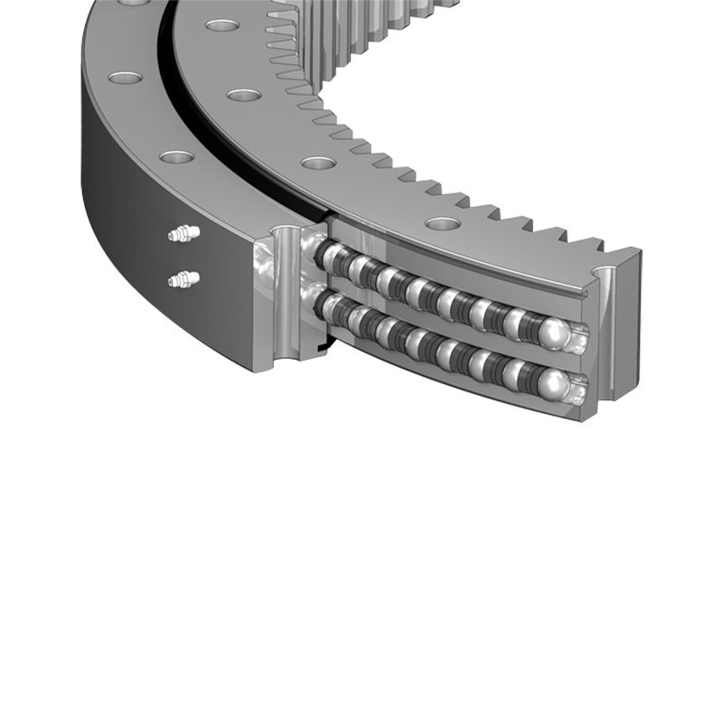
At the heavy end of the scale — port cranes, tunneling machines, large excavators — higher friction is accepted as the price of capacity, which is where a 13-series three-row roller slewing bearing earns its place: separate raceways carry axial, radial and moment loads independently, so no single row is compromised.
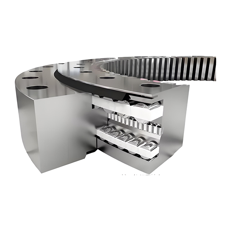 13 Series Three-Row Roller Slewing Bearing for Heavy LoadsSeparate raceways carry axial, radial and moment loads independently, making this 13 Series bearing suited to port cranes, tunneling machines and large excavators where capacity outweighs added friction. Alloy steel construction and simplified maintenance support demanding duty cycles.View Product →
What to Confirm With Your Supplier Before Ordering
- Friction torque data at your loads — starting and running values, not one blended figure.
- Test conditions — the load, speed and temperature at which those values were measured.
- Clearance or preload class — and what it does to expected resistance.
- Seal and grease specification — lip count, grease type and fill level, and cold-climate behavior.
- Gear quality and backlash — for geared rings, since mesh quality feeds directly into Mg.
- Acceptance criteria — a measured rotation-torque limit on the spin test before shipment.
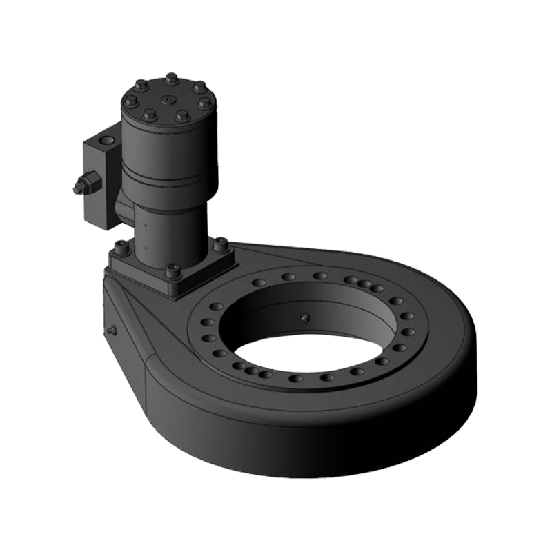
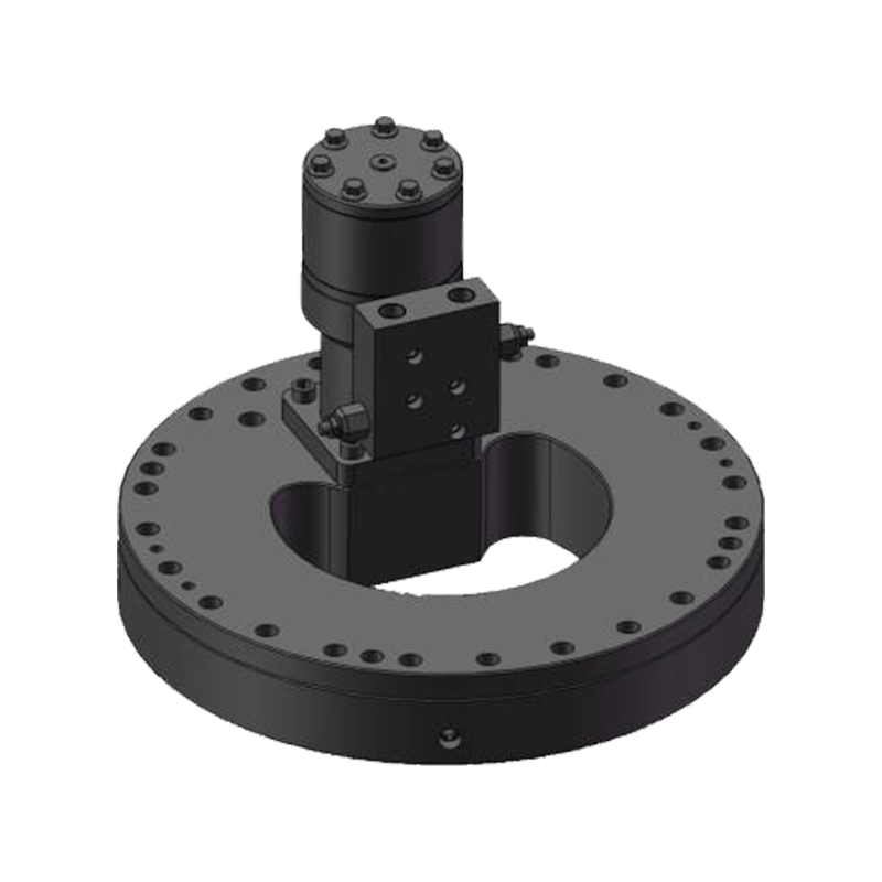
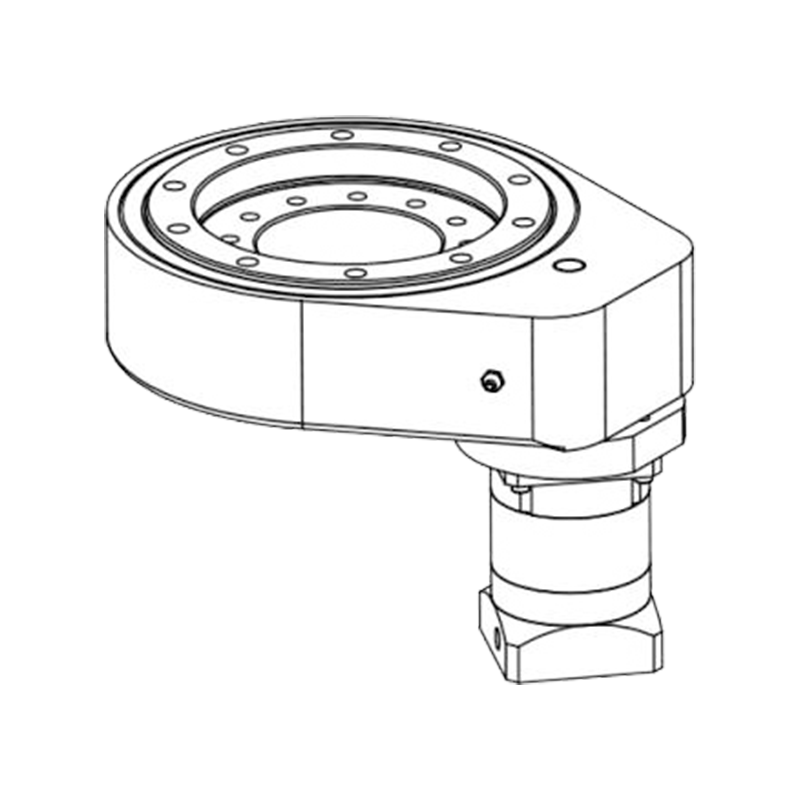
When friction plus working torque outgrows what a pinion and reducer arrangement handles economically, many buyers move to integrated units; a horizontal slewing drive packages the bearing, enclosed gearing and mounting housing as one matched assembly, so the torque chain is engineered as a system rather than assembled from parts.
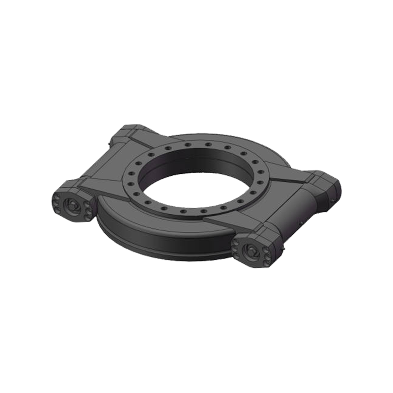 Horizontal Slewing Drive with Self-Locking FunctionThis integrated unit packages bearing, enclosed gearing and mounting housing as one matched assembly, so the torque chain is engineered as a system. Self-locking holds position under load without power, useful when friction and working torque exceed pin-and-reducer arrangements.View Product →
The torque of a slewing bearing is best treated as a system property, not a catalog constant. It is the sum of load, seal and gear friction; it spikes at start-up; and it moves with preload, temperature, lubrication and mounting quality. Share your real load cases — axial, radial, moment, speed and temperature range — with the bearing maker early, and ask for starting and running torque data against those loads. That single step prevents the most expensive failure mode in slewing applications: a machine that turns, but never quite as easily as the drawing promised.




Jiangsu Manchen Transmission Technology Co., Ltd. excels in creating custom, reliable, and precise slewing bearings for diverse industries, continuously innovating to meet the highest standards and seeking collaborative opportunities. Reliable and steady slewing bearings supplier in China.
Product links
Contact Us
-
Address:No. 8, Nanqiu Road, Huangtu Town, Jiangyin City,China
-
Tel:+86-13646122221
-
Phone:+86-18796936198
-
WhatsApp:+86 18796936198
-
E-mail:hedy@slewingbearingcn.com
-
E-mail:ma@slewingbearingcn.com
-
E-mail:vena@slewingbearingcn.com
