 English
 русский
 Español
 عربى
عربى

News

What Is a Three-Row Roller Slewing Bearing and How Does It Work?
 2026.06.08
 Industry news
Content
- 1 Defining the Three-Row Roller Slewing Bearing
- 2 Structural Anatomy: How the Three Rows Are Arranged
- 3 Working Principle: How Load Distribution Operates
- 4 Key Performance Characteristics
- 5 Comparison with Other Slewing Bearing Types
- 6 Primary Industrial Applications
- 7 Lubrication and Maintenance Considerations
- 8 Conclusion
Defining the Three-Row Roller Slewing Bearing
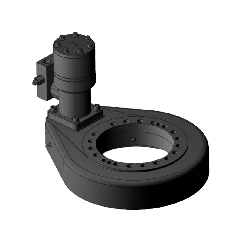
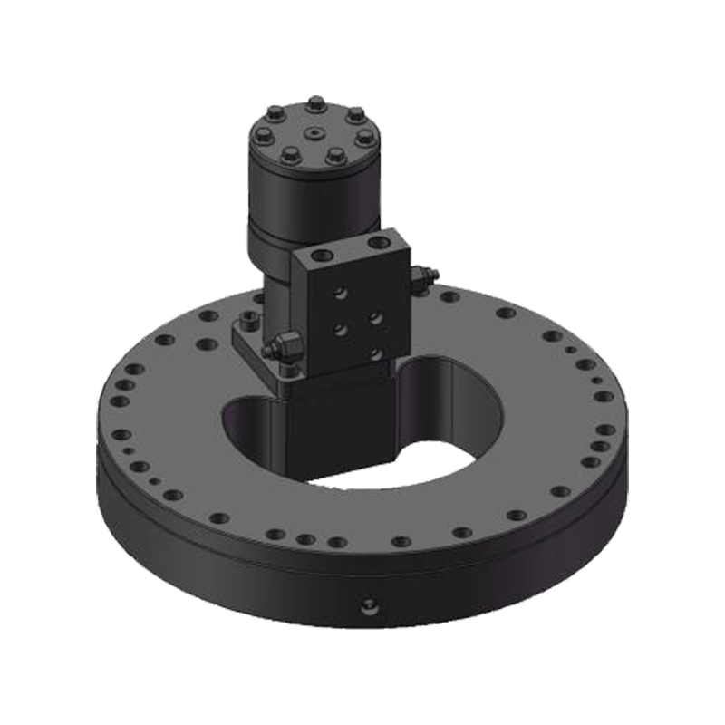
A three-row roller slewing bearing is a large-diameter, heavy-duty rotational support element specifically engineered to carry simultaneous combinations of axial loads, radial loads, and overturning moments — all within a single, compact bearing unit. Unlike standard ball bearings or single-row roller bearings, which are designed primarily for one dominant load direction, the three-row roller configuration distributes these three force types across three dedicated and geometrically separated rows of cylindrical rollers. This structural division of labor allows each row to be optimized independently for its specific load type, resulting in a bearing that achieves load capacities far beyond what any single-row design could manage within a comparable envelope.
The term "slewing" refers to the bearing's primary function: enabling slow, controlled rotational movement — typically less than 10 revolutions per minute — between two large structural components. This distinguishes slewing bearings from high-speed bearings used in motors or turbines. Three-row roller slewing bearings are found at the heart of some of the world's most demanding machinery, including crawler cranes, large excavators, offshore platforms, wind turbine yaw systems, and heavy industrial turntables, where reliability under extreme combined loading is non-negotiable.
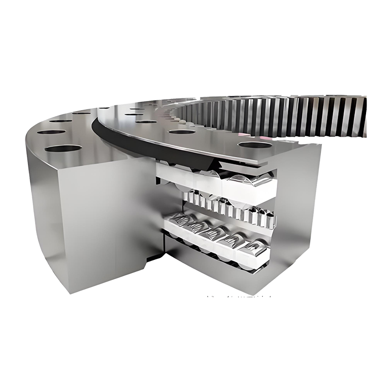
Structural Anatomy: How the Three Rows Are Arranged
The defining structural characteristic of this bearing type is its separation of load-carrying function across three distinct rows of cylindrical rollers, each housed in its own dedicated raceway within the bearing ring assembly. Understanding how these rows are physically arranged is essential to understanding how the bearing works under real operating conditions.
The Upper and Lower Axial Roller Rows
Two of the three roller rows are oriented horizontally — one positioned near the top of the bearing cross-section and one near the bottom. These are the axial rows, and their rollers run on horizontal raceways machined into the upper and lower bearing rings. The rollers in these rows are oriented with their axes pointing vertically, meaning they resist forces acting along the vertical axis — both downward compressive loads and upward tensile forces caused by overturning moments. When a crane boom extends and lifts a heavy load, the resulting moment attempts to tilt the upper ring relative to the lower ring; the upper axial row resists compression on the load side while the lower axial row resists uplift on the opposite side. Together, these two rows manage the moment couple that keeps the rotating structure stable.
The Central Radial Roller Row
Between the two axial rows sits the third row — the radial row. These rollers are oriented with their axes pointing horizontally, running on vertical raceways machined into the inner surfaces of the outer ring and the outer surface of the inner ring. Their function is to resist radial loads — forces that act horizontally and attempt to displace the inner ring laterally relative to the outer ring. In a crane on a ship or an excavator operating on uneven ground, significant lateral forces are generated by wind, dynamic movement, and uneven ground reaction. The radial row absorbs these forces and maintains the concentric alignment of the two bearing rings throughout operation.
The Ring and Raceway Structure
The bearing assembly typically consists of three rings rather than the two rings found in conventional bearings. The outer ring and inner ring form the primary structural members, while an intermediate ring — often called the middle ring — separates the upper axial raceway from the lower axial raceway and provides the mounting surface for the radial row. This three-ring construction is what physically enables the three-row arrangement and gives the bearing its exceptional ability to handle combined loads without transferring stress between rows.
Working Principle: How Load Distribution Operates
The working principle of a three-row roller slewing bearing is rooted in the fundamental mechanics of roller contact and the geometric separation of load paths. When the bearing is subjected to real-world operating conditions, multiple forces act on it simultaneously, and the bearing must resolve each of these into a stable, well-distributed contact stress state without overloading any individual roller or raceway.
Cylindrical Line Contact vs. Ball Point Contact
A critical aspect of the working principle is the use of cylindrical rollers rather than balls. Balls make point contact with their raceways — a theoretical single point that in practice becomes a small elliptical contact patch under load. Cylindrical rollers, by contrast, make line contact along their entire length with the raceway surface. This dramatically increases the contact area, which in turn reduces the Hertzian contact stress (pressure per unit area) for any given applied load. The result is that cylindrical roller bearings can carry substantially higher loads than equivalent-sized ball bearings before reaching the stress limits of their raceway material. For slewing bearings in heavy machinery — where loads routinely reach hundreds or thousands of kilonewtons — this difference in contact geometry is the fundamental reason roller designs are specified over ball designs.
Moment Resolution Through the Axial Couple
When an overturning moment is applied to the bearing — for example, when a crane lifts an off-center load that tries to tilt the upper structure — this moment is resolved into a force couple acting on the two axial roller rows. The row on the loaded side experiences increased compressive force, while the row on the opposite side experiences a tensile reaction force that pulls the rings apart. The vertical separation distance between the two axial rows — the moment arm — determines how large these reaction forces are for a given moment magnitude. A larger vertical separation reduces the force required in each row, which is why three-row roller slewing bearings are typically designed with the maximum feasible vertical distance between the two axial raceways.
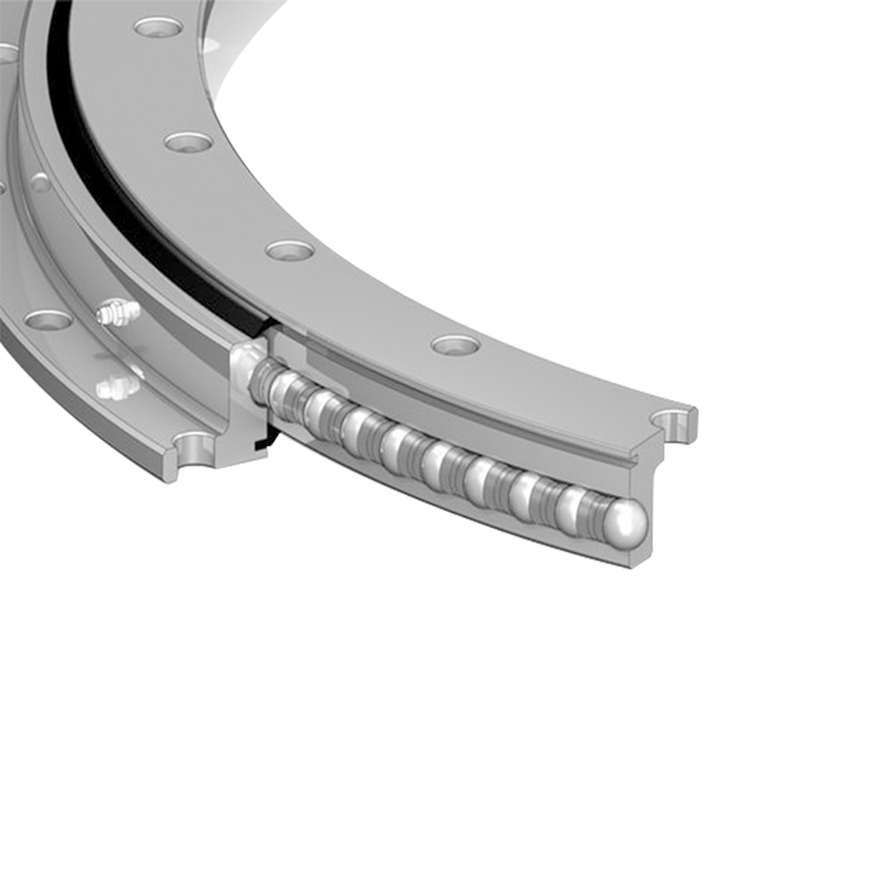
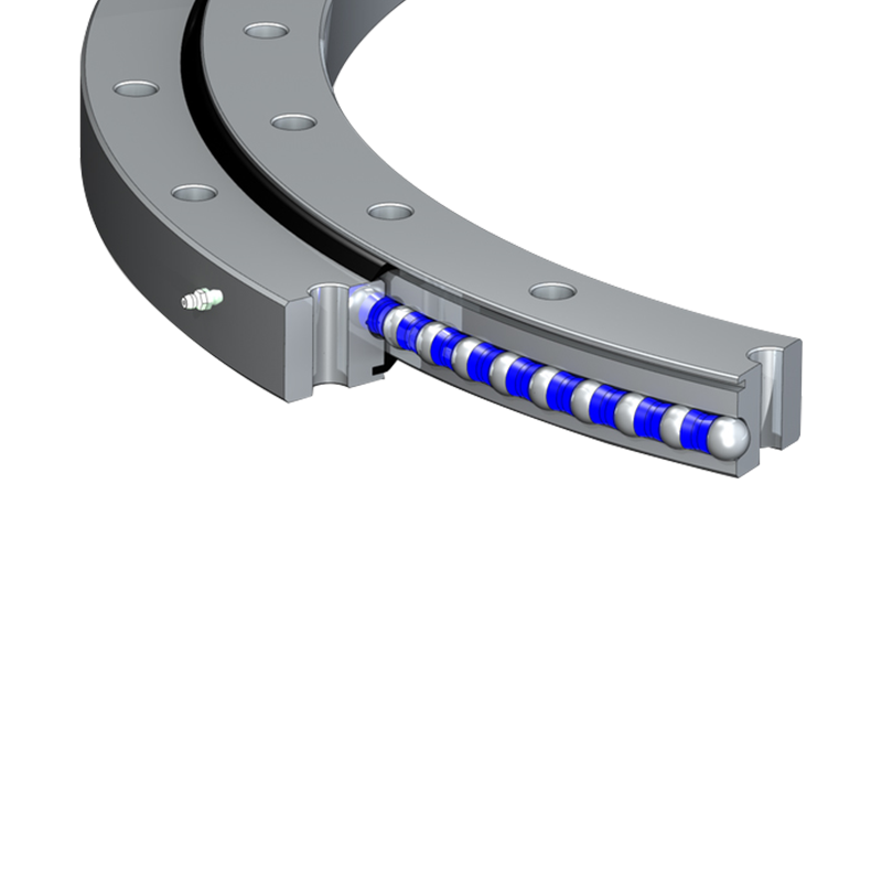
Roller Guidance and Cage Function
The cylindrical rollers in each row are guided by cages or spacers that maintain uniform circumferential spacing between rollers, prevent roller skewing, and ensure that load is distributed evenly around the full circumference of the bearing rather than concentrated in one area. In some designs, especially for very large bearings, individual spacer blocks replace a full cage, allowing more rollers to be packed into each row and further increasing load capacity. Proper roller guidance is essential to the smooth, low-friction rotation that slewing bearings are expected to deliver over long service lives.
Key Performance Characteristics
The combination of three dedicated roller rows and cylindrical line contact geometry gives the three-row roller slewing bearing a performance profile that is distinctly superior to other slewing bearing types in heavy-load applications. The following characteristics define its operational capability:
- Exceptional load capacity: The three-row design achieves the highest static and dynamic load ratings of any slewing bearing configuration, making it the standard choice for machinery with lift capacities measured in hundreds of tonnes.
- High moment resistance: The wide axial separation between the two axial roller rows creates a large moment arm, enabling the bearing to resist enormous tilting moments without deformation or raceway damage.
- Rigid ring structure: The three-ring construction provides excellent resistance to ring deflection under load, maintaining raceway geometry and roller contact conditions even under peak loading events.
- Low operating friction: Despite carrying very high loads, cylindrical rollers produce lower rolling friction than sliding contact elements, reducing drive torque requirements and energy consumption in slewing drives.
- Long service life: The distributed load path reduces peak stress at any single contact point, contributing to fatigue life that meets the demanding duty cycles of construction and industrial machinery.
Comparison with Other Slewing Bearing Types
To appreciate where the three-row roller design fits in the broader family of slewing bearings, it is useful to compare it directly against the other common configurations used in rotating machinery.
| Bearing Type | Load Capacity | Moment Resistance | Complexity | Typical Application |
| Single-Row Ball | Low to Medium | Low | Simple | Light machinery, solar trackers |
| Double-Row Ball | Medium | Medium | Moderate | Medium cranes, turntables |
| Cross-Roller | Medium to High | High | Moderate | Robotics, precision equipment |
| Three-Row Roller | Very High | Very High | High | Crawler cranes, excavators, offshore |
Primary Industrial Applications
The three-row roller slewing bearing's exceptional load and moment capacity makes it the standard specification for the most demanding rotational joints in heavy industry and construction. Its applications share a common requirement: large-diameter rotation under simultaneous and significant axial, radial, and moment loading.
- Crawler and lattice boom cranes: The upperworks-to-undercarriage connection on large crawler cranes uses three-row roller slewing bearings to support boom loads that can exceed several hundred tonnes while allowing full 360-degree rotation.
- Large hydraulic excavators: The house rotation joint on large mining excavators relies on three-row roller designs to handle the combined weight of the upper structure, bucket loads, and dynamic digging forces.
- Offshore drilling platforms: Turret moorings, crane pedestals, and rotating deck equipment on offshore installations require the high moment resistance and corrosion-resistant variants of three-row roller bearings.
- Wind turbine yaw systems: Large multi-megawatt wind turbines use three-row roller slewing bearings to rotate the nacelle to face changing wind directions, where the bearing must resist enormous overturning moments from rotor thrust.
- Heavy industrial positioners and turntables: Steel mill equipment, heavy fabrication positioners, and large material handling turntables use these bearings to provide stable, low-friction rotation under massive static loads.
Lubrication and Maintenance Considerations
Proper lubrication is fundamental to the working life of a three-row roller slewing bearing. Each of the three roller rows operates on its own set of raceways, and all contact surfaces must be kept supplied with appropriate grease to prevent metal-to-metal contact, reduce friction, and inhibit corrosion. Most large slewing bearings are equipped with grease nipples or lubrication channels drilled through the rings that allow grease to be injected directly into each raceway cavity without disassembly. The bearing should be slowly rotated during greasing to ensure full circumferential coverage of all roller contacts.
Sealing systems — typically multi-lip rubber seals fitted into grooves at the inner and outer circumference of the bearing — protect the raceway cavities from the ingress of water, dust, and abrasive particles that would rapidly accelerate wear. In outdoor or offshore environments, seal integrity is particularly critical and should be inspected regularly as part of a structured maintenance program. Bearing ring bolts must also be checked periodically for correct preload, as bolt loosening under cyclic loading can allow ring deflection that alters raceway geometry and accelerates fatigue damage.
Conclusion
The three-row roller slewing bearing is a precisely engineered solution to one of mechanical engineering's most demanding challenges: supporting simultaneous axial loads, radial loads, and overturning moments on a large rotating joint under heavy-duty cyclic conditions. Its three-ring structure, three dedicated roller rows, and cylindrical line-contact geometry work together to deliver load capacities and moment resistance that no other bearing configuration of comparable diameter can match. For engineers specifying large rotating machinery — from crawler cranes to offshore platforms — understanding the definition and working principle of this bearing type is essential to making informed design decisions that ensure safety, reliability, and long service life in the field.


Jiangsu Manchen Transmission Technology Co., Ltd. excels in creating custom, reliable, and precise slewing bearings for diverse industries, continuously innovating to meet the highest standards and seeking collaborative opportunities. Reliable and steady slewing bearings supplier in China.
Product links
Contact Us
-
Address:No. 8, Nanqiu Road, Huangtu Town, Jiangyin City,China
-
Tel:+86-13646122221
-
Phone:+86-18796936198
-
WhatsApp:+86 18796936198
-
E-mail:hedy@slewingbearingcn.com
-
E-mail:ma@slewingbearingcn.com
-
E-mail:vena@slewingbearingcn.com
