 English
 русский
 Español
 عربى
عربى

News
 Home / News / Industry news / What Are the Five Most Important Things to Know About Horizontal Slewing Drives?
 What Are the Five Most Important Things to Know About Horizontal Slewing Drives?
 2026.06.05
 Industry news
Content
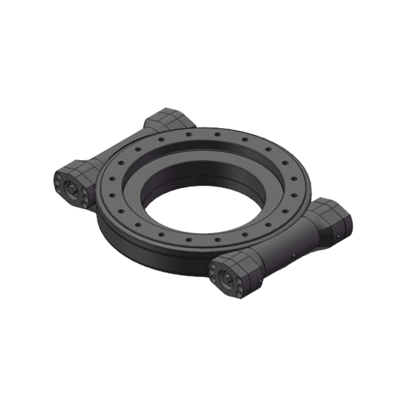
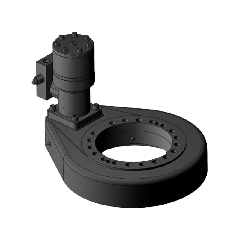
What Is a Horizontal Slewing Drive?
A horizontal slewing drive is a specialized mechanical component designed to provide controlled rotational movement in a horizontal plane. It combines a slewing ring bearing with a worm gear or other drive mechanism into a single, compact housing unit. The result is a self-contained system capable of transmitting high torque while supporting axial, radial, and moment loads simultaneously — all without requiring additional support structures.
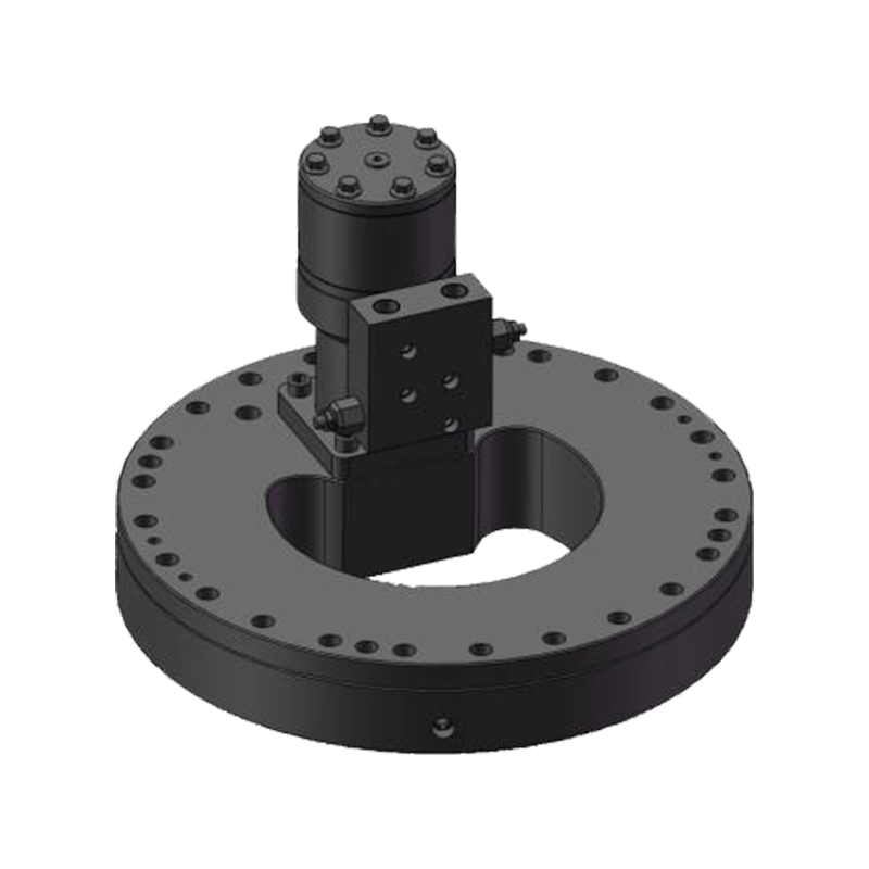
Unlike standard gear reducers or turntables, horizontal slewing drives are engineered specifically for applications where the axis of rotation is vertical and the load sits on top of the drive. This orientation is what distinguishes them from vertical slewing drives and makes them uniquely suited to industries that require precise, low-speed rotation under heavy loads. They are often rated by output torque, holding torque, and tilt moment capacity — three values that engineers must evaluate carefully during selection.
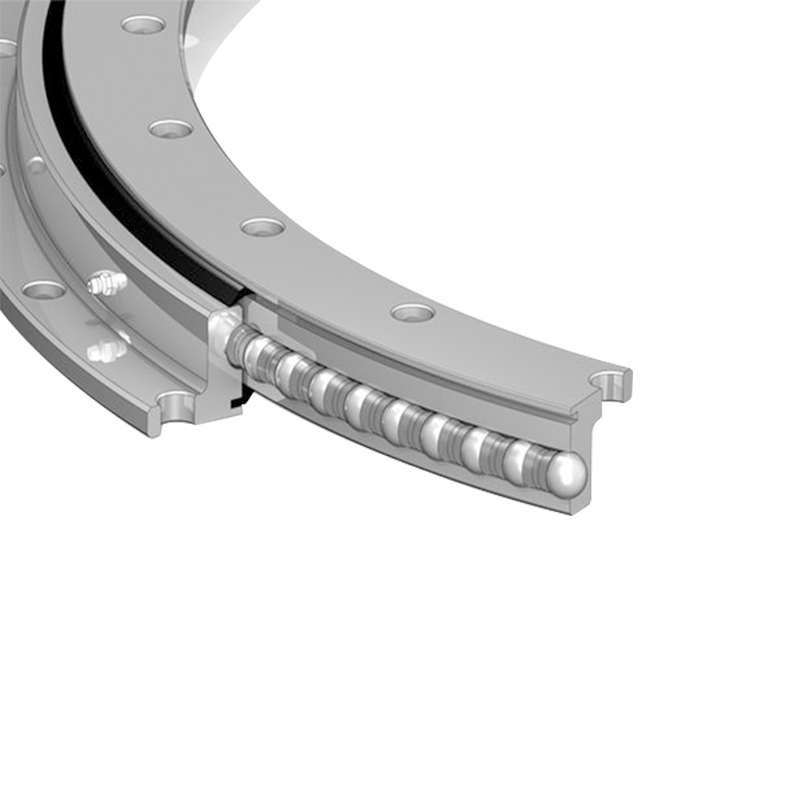
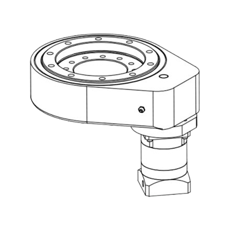
How Horizontal Slewing Drives Work
The core operating principle of a horizontal slewing drive relies on the interaction between a worm shaft and a ring gear embedded inside the slewing bearing. When a motor turns the worm shaft, it drives the ring gear to rotate the output flange at a significantly reduced speed. This gear reduction provides the high torque output needed for demanding industrial tasks while maintaining smooth, precise positioning.
Most horizontal slewing drives use a worm gear configuration because of its inherent self-locking capability. This means that when the motor is not actively driving the shaft, the mechanism holds its position without additional braking systems. This is a critical safety advantage in applications like solar trackers or cranes where unintended movement could cause damage or injury. More advanced models may incorporate helical or planetary gear systems to achieve higher efficiency while sacrificing some degree of self-locking.
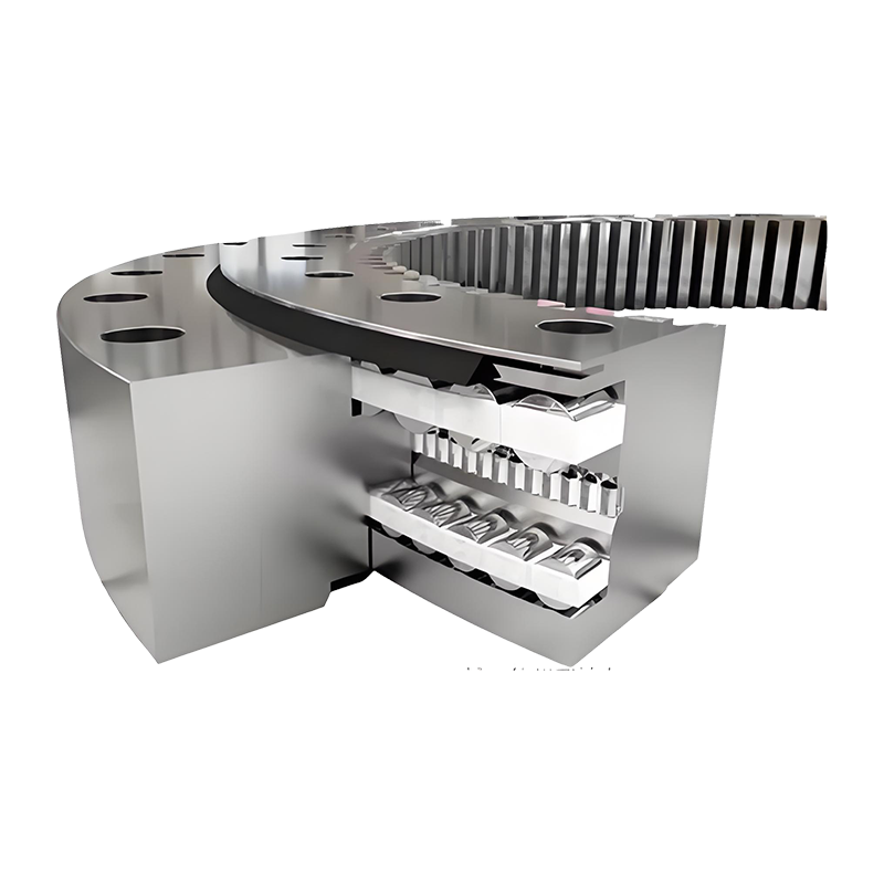
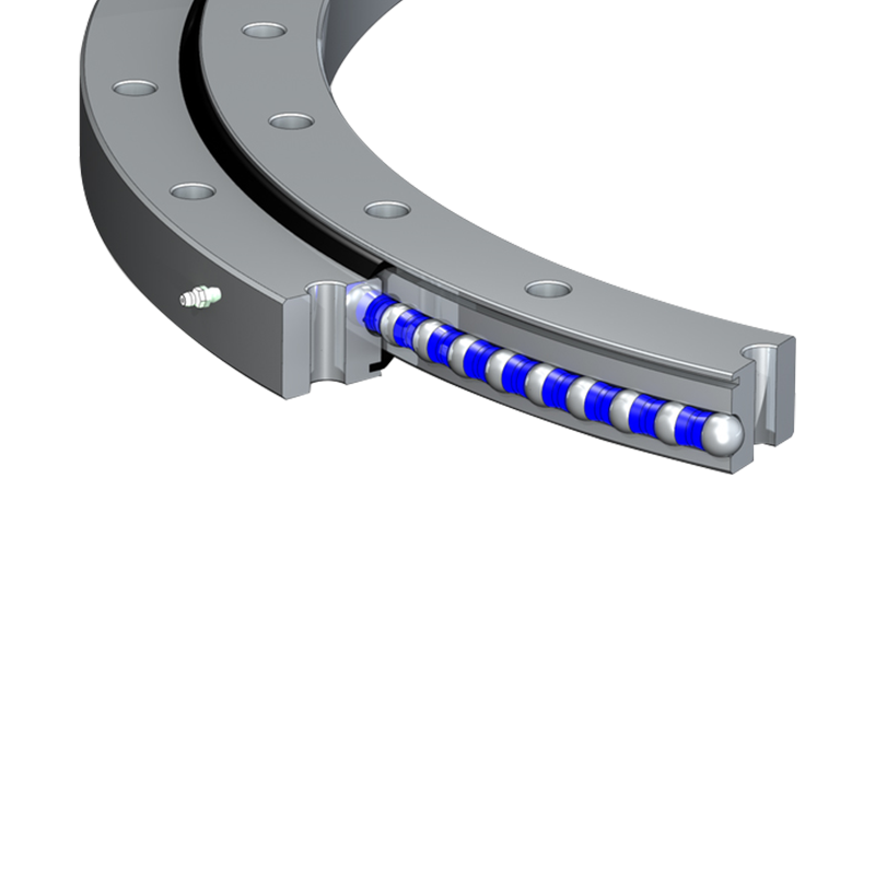
Key Internal Components
- Worm shaft: the primary input driven by a motor
- Slewing ring bearing: supports loads while enabling rotation
- Output flange: connects to the rotating load or structure
- Housing: encloses and protects the gear assembly
- Seals and grease fittings: ensure long-term lubrication and protection
Common Applications of Horizontal Slewing Drives
Horizontal slewing drives are found across a wide range of industries, anywhere that precise horizontal rotation under load is required. Their versatility makes them one of the most widely used rotary drive solutions in modern engineering. Understanding where they are most commonly deployed helps clarify what performance characteristics matter most in any given use case.
Solar energy is one of the most prominent application areas. Single-axis solar trackers use horizontal slewing drives to rotate photovoltaic panels throughout the day, following the sun from east to west. Because these systems operate outdoors year-round, the drives must be weatherproof, capable of handling wind loads, and reliable enough to operate with minimal maintenance over a 20-plus-year lifespan.
Beyond solar, horizontal slewing drives are essential in the following sectors:
- Construction equipment: truck-mounted cranes, aerial work platforms, and concrete pump trucks all rely on slewing drives for their rotating booms
- Satellite and radar systems: antenna positioning requires high precision and reliable holding torque under dynamic wind conditions
- Agricultural machinery: irrigation systems and spreading equipment use slewing drives to control rotation speed and direction
- Marine applications: deck cranes and rotating platforms on vessels require corrosion-resistant slewing drives
- Industrial automation: robotic arms, rotary indexing tables, and automated guided vehicles use compact slewing drives for controlled positioning
Understanding Load Ratings and Performance Specifications
One of the most critical aspects of selecting a horizontal slewing drive is correctly interpreting its load ratings. Manufacturers publish multiple load values, and confusing them can lead to premature failure or unsafe installations. There are three primary load types that any engineer or buyer must understand before making a specification decision.
| Load Type | Definition | Typical Unit |
| Output Torque | The rotational force the drive can deliver to the load | N·m or kN·m |
| Holding Torque | The maximum torque the drive can resist when stationary | N·m or kN·m |
| Tilting Moment | The bending load capacity when an offset force is applied | kN·m |
| Axial Load | Vertical downward force the bearing ring can support | kN |
When specifying a horizontal slewing drive, always apply a safety factor — typically between 1.5 and 2.0 — over the calculated working load. This accounts for dynamic forces, shock loads, and environmental stresses that are difficult to predict precisely. It is also important to consider duty cycle: a drive used intermittently for short bursts will have a different thermal profile than one running continuously, which affects long-term reliability.
Maintenance Best Practices for Long Service Life
Horizontal slewing drives are built for durability, but they are not maintenance-free. A consistent maintenance schedule dramatically extends service life and reduces the risk of unexpected downtime. Because these drives are often installed in remote or hard-to-access locations — such as on top of solar arrays or the booms of cranes — it is especially important to follow preventive maintenance protocols rather than waiting for problems to emerge.
Lubrication
Proper lubrication is the single most important maintenance task for any slewing drive. Both the worm gear and the slewing ring bearing have separate lubrication requirements. The ring gear typically requires grease injected through dedicated nipples, while the worm gear housing contains gear oil that must be checked and replaced at manufacturer-specified intervals. Using the wrong lubricant viscosity or allowing grease to degrade will accelerate wear significantly.
Seal Inspection and Replacement
Seals protect the internal components from dust, moisture, and contaminants. In outdoor applications especially, seals should be inspected at least annually. Cracked or hardened seals allow water ingress, which leads to corrosion of the bearing raceway and rapid deterioration of the gear teeth. Replacing seals proactively is far less costly than replacing an entire drive assembly after contamination damage has occurred.
Backlash and Torque Monitoring
Over time, gear wear increases backlash — the small amount of play between meshing gear teeth. Monitoring backlash is a useful indicator of internal wear. Some manufacturers offer adjustable preload mechanisms that can compensate for minor wear and restore positioning accuracy. If backlash exceeds the manufacturer's acceptable threshold, the drive should be serviced or replaced to prevent cascading damage to connected equipment.
How to Select the Right Horizontal Slewing Drive
Choosing the correct horizontal slewing drive for a specific application involves balancing multiple technical and logistical factors. A drive that is undersized will fail prematurely, while an oversized drive adds unnecessary cost and weight. The selection process should follow a systematic approach based on the actual operating conditions rather than rule-of-thumb estimates.
Start by calculating the required output torque based on the load weight, center of gravity offset, and friction coefficients of any rolling or sliding contacts in the system. Add dynamic factors for acceleration and deceleration phases. Next, determine whether the application requires continuous rotation or oscillating movement, as this affects both gear selection and lubrication strategy. Finally, assess the environmental conditions — temperature range, humidity, exposure to chemicals or salt air — to determine sealing requirements and material choices for the housing and fasteners.
Additional selection criteria to evaluate include:
- Motor interface compatibility: confirm that the drive's input shaft matches your motor's output dimensions and coupling type
- Output speed: verify that the gear ratio delivers the rotation speed your application demands without overheating the motor
- Mounting configuration: ensure the bolt pattern and flange dimensions align with your structural design
- Certification requirements: some industries require drives to meet specific standards such as ISO, CE, or ATEX for hazardous environments
- Supplier support: choose manufacturers who provide detailed technical datasheets, application engineering support, and accessible spare parts
Working directly with the manufacturer's engineering team during the selection phase is strongly recommended for complex or high-stakes installations. Providing your full load case data — including worst-case scenarios — allows the supplier to validate the selection and flag potential issues before the drive is ever installed in the field.


Jiangsu Manchen Transmission Technology Co., Ltd. excels in creating custom, reliable, and precise slewing bearings for diverse industries, continuously innovating to meet the highest standards and seeking collaborative opportunities. Reliable and steady slewing bearings supplier in China.
Product links
Contact Us
-
Address:No. 8, Nanqiu Road, Huangtu Town, Jiangyin City,China
-
Tel:+86-13646122221
-
Phone:+86-18796936198
-
WhatsApp:+86 18796936198
-
E-mail:hedy@slewingbearingcn.com
-
E-mail:ma@slewingbearingcn.com
-
E-mail:vena@slewingbearingcn.com
