

 EN
EN  English
 русский
 Español
 عربى
عربى

News
 Home / News / Industry news / How Does a Three-Row Roller Slewing Bearing Work — and Why Does It Matter for Heavy Machinery?
 How Does a Three-Row Roller Slewing Bearing Work — and Why Does It Matter for Heavy Machinery?
 2026.05.27
 Industry news
Content
What Is a Three-Row Roller Slewing Bearing?
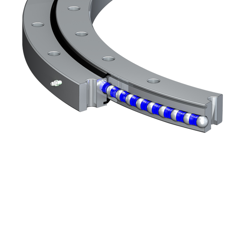
A three-row roller slewing bearing is a large-diameter, precision-engineered rotary component designed to handle simultaneous axial loads, radial loads, and tilting moments — often all at once. Unlike standard bearings that focus on a single load direction, this design incorporates three separate rows of cylindrical rollers, each assigned a specific load-handling function. This division of labor is what makes the three-row roller configuration one of the most capable slewing bearing types available in the heavy-duty machinery sector.
These bearings are typically manufactured with diameters ranging from 400 mm to well over 10,000 mm, making them suitable for the largest rotating structures in industrial and infrastructure applications. They are used where conventional bearings would be insufficient or impractical, and where the structural integrity of a rotating joint is critical to the machine's safe operation.
Core Structural Components
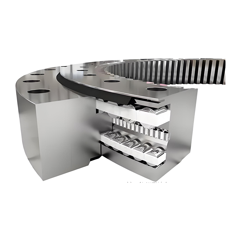
Understanding how a three-row roller slewing bearing works begins with understanding its structure. The bearing consists of the following primary elements:
- Outer Ring: A large structural ring that typically connects to the stationary part of the machine, such as a base frame or platform. It houses the raceways for the upper and lower axial roller rows.
- Inner Ring: Rotates relative to the outer ring and is mounted to the rotating superstructure. It contains the raceways for the radial roller row and interfaces with the axial rows.
- Upper Axial Roller Row: Positioned horizontally near the top of the bearing cross-section, this row handles downward axial forces and contributes to tilting moment resistance.
- Lower Axial Roller Row: Mirroring the upper row at the bottom of the cross-section, it handles upward axial forces and provides the other half of the tilting moment couple.
- Radial Roller Row: Oriented vertically between the inner and outer rings, this row exclusively manages radial (horizontal) forces acting on the bearing.
- Spacers and Cages: Maintain correct spacing between rollers, preventing contact and ensuring smooth, consistent rolling motion throughout the full 360° of rotation.
- Seals: Protect the internal rolling elements and raceways from contamination by dust, water, and debris — critical for outdoor and harsh-environment operations.
- Gear Teeth (optional): Many three-row roller slewing bearings feature integral gear teeth — internal, external, or both — allowing direct coupling to a drive pinion for rotation control.
How Each Roller Row Functions
The genius of the three-row design lies in the deliberate separation of load paths. Each roller row is geometrically and structurally optimized to carry a specific type of force with maximum efficiency.
Axial Load Handling (Upper and Lower Rows)
The upper and lower axial roller rows are arranged in horizontal planes — one at the top and one at the bottom of the bearing's cross-section. Their raceways are oriented so that the cylindrical rollers roll along flat, horizontal surfaces. When a vertical (axial) force is applied — such as the weight of a crane boom or a rotating platform loaded with cargo — the appropriate axial row absorbs this load in compression. Downward forces are taken by the upper row; upward forces (tension or lift-off) are resisted by the lower row.
The vertical separation between these two rows creates a moment arm. This is the key to the bearing's superior tilting moment capacity. A tilting moment — which occurs when a load is applied off-center, causing the rotating structure to try to tip — is resolved as a force couple: compressive load on one axial row and tensile load on the other. The greater the vertical distance between the rows, the greater the moment that can be resisted without exceeding the rollers' contact stress limits.
Radial Load Handling (Middle Row)
Located between the upper and lower axial rows, the radial roller row is oriented vertically. Its rollers run along vertical raceways machined into the inner and outer rings. When horizontal forces act on the bearing — such as wind loads on a tower crane, lateral shocks in excavator operations, or horizontal thrust from hydraulic actuators — this row absorbs them entirely. The radial row does not interfere with the axial rows' function; each operates independently within its own raceway, which eliminates cross-loading and ensures long, predictable service life.
Load Capacity Comparison
To appreciate why three-row roller slewing bearings are specified for the most demanding applications, it helps to compare their load capacity profile against other slewing bearing types:
| Bearing Type | Axial Load | Radial Load | Tilting Moment | Typical Application |
| Single-Row Ball | Moderate | Low | Low | Light cranes, solar trackers |
| Double-Row Ball | High | Moderate | Moderate | Medium excavators, turntables |
| Cross-Roller | High | Moderate | High | Robots, precision indexing |
| Three-Row Roller | Very High | Very High | Very High | Heavy cranes, offshore, shields |
The three-row roller bearing outperforms all alternatives across every load category simultaneously, which is why it is the standard choice for the most extreme load environments.
Rotation Mechanism and Drive Integration
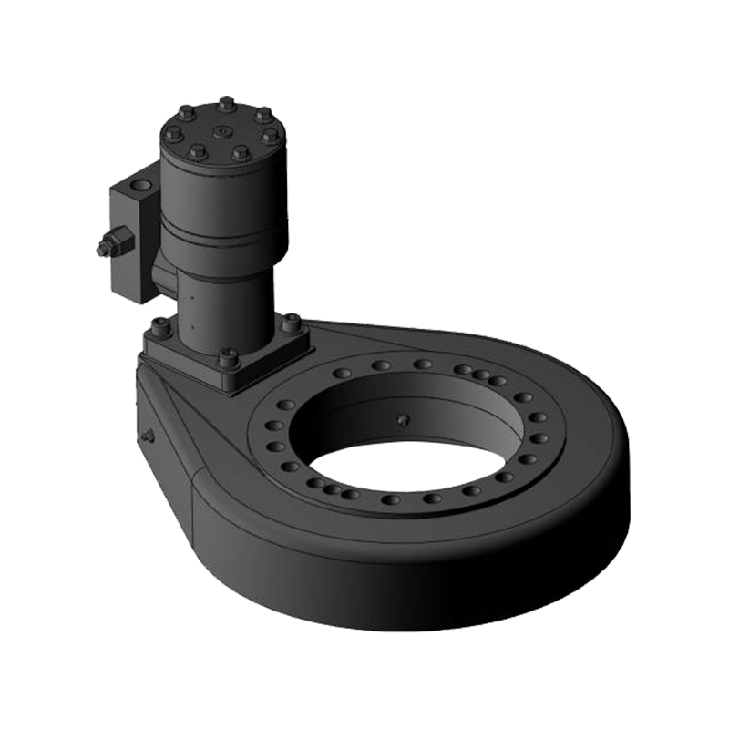
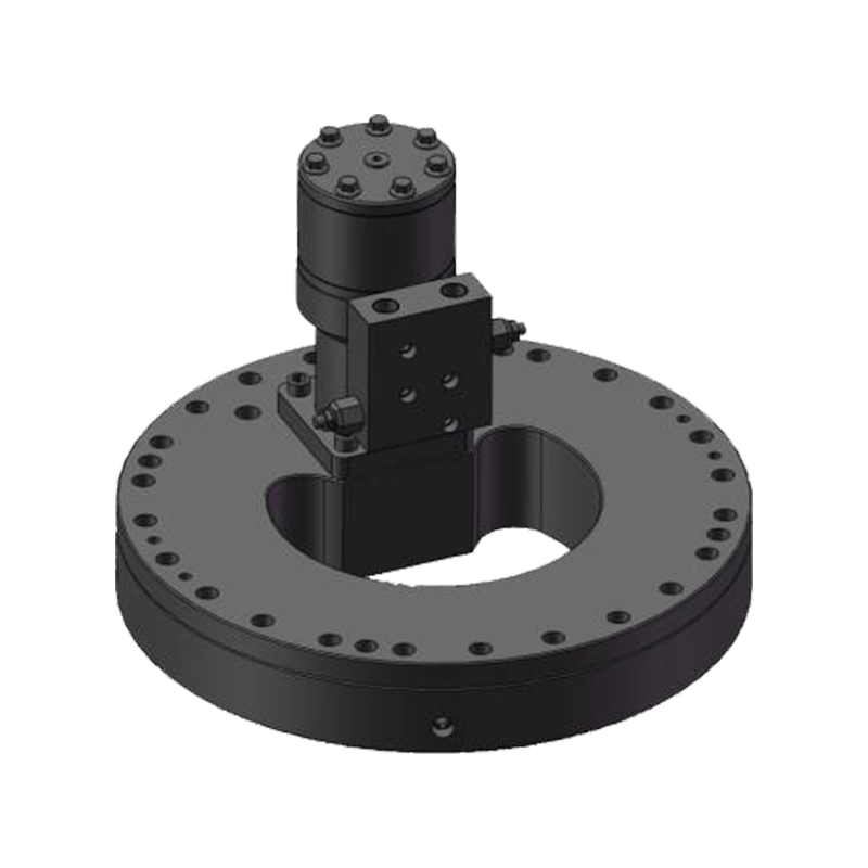
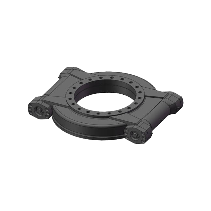
In most working installations, a three-row roller slewing bearing does not rotate freely on its own — it is driven by an external power system. The most common drive method involves a motor-gearbox unit coupled to a pinion gear that meshes with gear teeth machined into the bearing ring. Depending on the application, the gear teeth may be on the outer ring (external gear) or the inner ring (internal gear).
Internal gear configurations allow a more compact installation and provide a higher gear ratio for a given diameter. External gear configurations offer easier pinion access and replacement. In some high-power applications — such as offshore crane pedestals or large industrial positioners — multiple drive pinions are positioned around the circumference to distribute torque evenly and prevent gear tooth overload.
When no gear teeth are required (as in some hydraulically driven pivot joints), the bearing rings are simply bolted to their respective structures and rotation is achieved through fluid power acting on an arm or actuator. In all cases, the bearing's rolling elements transmit the structural loads while the drive system handles only the rotational torque — a clean functional separation that extends the life of both systems.
Lubrication and Maintenance Principles
Because three-row roller slewing bearings carry very high loads over large diameters, lubrication is a non-negotiable operational requirement. Inadequate lubrication leads to surface fatigue, fretting corrosion between rollers and raceways, and accelerated wear of the gear teeth.
Grease lubrication is the most common approach. The bearing typically has multiple grease fittings distributed around its circumference — sometimes as many as one fitting every 30° — to ensure uniform coverage of all roller rows. Automatic lubrication systems are frequently installed on continuous-operation machines to deliver precise grease quantities at programmed intervals without requiring manual access.
Gear teeth are lubricated separately, usually with open gear grease applied by a spray or drip system. The grease must be compatible with the operating temperature range and resistant to water washout in outdoor environments. Maintenance schedules should include periodic inspection of seal integrity, since a failed seal allows contamination into the bearing cavity and dramatically accelerates degradation.
Typical Applications in Industry
The combination of exceptional multi-axis load capacity and large diameter makes the three-row roller slewing bearing the preferred choice in several demanding sectors:
- Crawler and Tower Cranes: The slewing ring connects the upperworks (boom, counterweight, cab) to the undercarriage, enduring constant axial load from the crane's own weight plus high tilting moments from lifted loads at extended radii.
- Offshore Platforms and Pipe-Laying Vessels: Subsea cranes and thruster pedestals operate in corrosive salt-spray environments with dynamic wave-induced loads — exactly the multi-axis, high-magnitude loading the three-row design handles best.
- Tunnel Boring Machines (TBMs): The main bearing of a TBM must support the enormous axial thrust of the cutterhead pressing against rock, combined with the radial weight of the rotating head assembly — a simultaneous load combination few bearing designs can handle.
- Large Excavators and Mining Equipment: The swing bearing connecting the upper house to the undercarriage must manage payload weight, digging reaction forces, and travel-induced dynamic loads continuously throughout a shift.
- Wind Turbine Yaw and Pitch Systems: Large turbines use three-row roller bearings in their yaw systems (rotating the nacelle to face the wind) where consistent performance under combined gravity and wind loads over a 20+ year service life is essential.
- Ladle Turrets and Metallurgical Equipment: In steelmaking, ladle turrets rotate massive vessels of molten metal — requiring bearings that can sustain both extreme vertical loads and the thermal environment of a steel plant.
Key Selection Parameters for Engineers
When specifying a three-row roller slewing bearing for a new application, engineers must evaluate several interdependent parameters to ensure correct sizing and long service life:
- Static and dynamic load ratings: The bearing must satisfy both peak (static) load conditions and the cumulative fatigue loading from dynamic operation. Manufacturers publish load rating tables; always verify against the actual load spectrum, not just the maximum load.
- Tilting moment capacity: This is often the governing design criterion. It depends on the vertical distance between the axial roller rows and the roller diameter and length.
- Mounting flange stiffness: A slewing bearing performs only as well as its mounting structure. Insufficient flange rigidity causes ring distortion under load, leading to uneven roller contact and premature raceway fatigue.
- Rotational speed: Three-row roller slewing bearings are designed for slow-speed operation, typically below 5 rpm. Higher speeds require special lubrication provisions and may affect bearing selection.
- Material and surface treatment: For corrosive or high-temperature environments, material selection (stainless steel inserts, special alloys) and surface coatings become critical to service life.
A three-row roller slewing bearing, correctly selected, sized, installed, and maintained, is one of the most reliable large structural joints available to machine designers. Its architecture — three independent roller rows, each optimized for a distinct load direction — reflects a fundamental engineering principle: when loads are complex and continuous, the most robust solution is one that handles each component of that load with a dedicated, purpose-built mechanism.


Jiangsu Manchen Transmission Technology Co., Ltd. excels in creating custom, reliable, and precise slewing bearings for diverse industries, continuously innovating to meet the highest standards and seeking collaborative opportunities. Reliable and steady slewing bearings supplier in China.
Product links
Contact Us
-
Address:No. 8, Nanqiu Road, Huangtu Town, Jiangyin City,China
-
Tel:+86-13646122221
-
Phone:+86-18796936198
-
WhatsApp:+86 18796936198
-
E-mail:hedy@slewingbearingcn.com
-
E-mail:ma@slewingbearingcn.com
-
E-mail:vena@slewingbearingcn.com
