 English
 русский
 Español
 عربى
عربى

News
 Home / News / Industry news / What Is a Single Row Cross-Roller Slewing Bearing and How Does It Work?
 What Is a Single Row Cross-Roller Slewing Bearing and How Does It Work?
 2026.06.16
 Industry news
Content
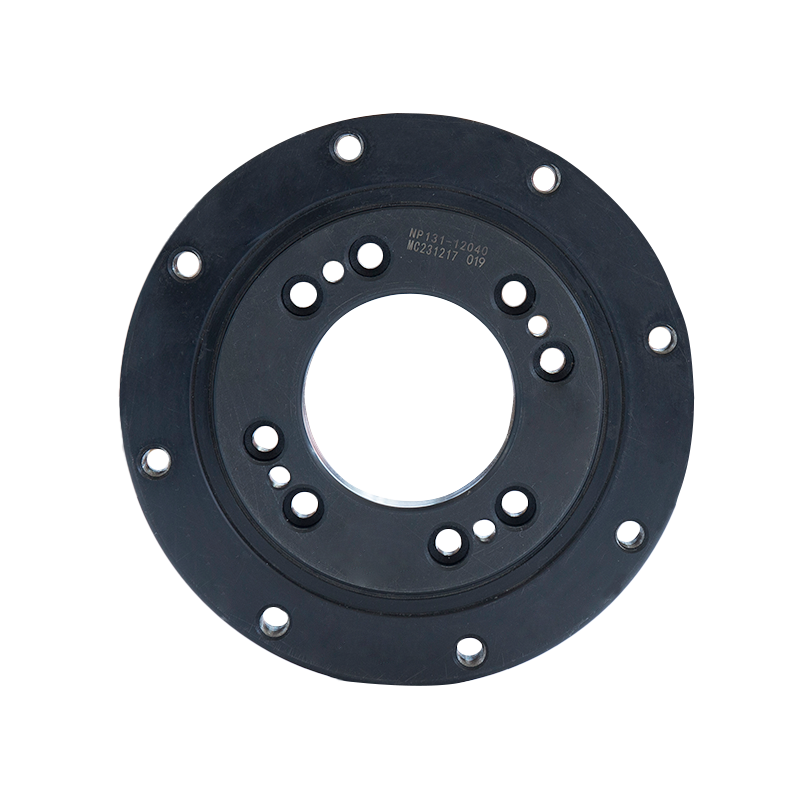
What Is a Single Row Cross-Roller Slewing Bearing?
A single row cross-roller slewing bearing is a large-diameter precision bearing designed to support axial loads, radial loads, and tilting moments simultaneously through a single compact ring assembly. Unlike conventional rolling element bearings that use separate rows for different load directions, the cross-roller design arranges cylindrical rollers in an alternating perpendicular pattern within a single raceway groove. Each roller is oriented at 90 degrees to its neighbor, meaning one roller handles axial force while the next handles radial force, and this alternating arrangement continues around the full circumference of the bearing ring.
This configuration allows a single row cross-roller slewing bearing to replace what would otherwise require multiple separate bearing assemblies — typically a combination of thrust bearings and radial bearings — within one space-efficient unit. The result is a bearing that delivers exceptional rigidity, high load capacity relative to its cross-sectional dimensions, and precise rotational accuracy, making it indispensable in applications where structural compactness and performance under combined loading are both critical requirements.
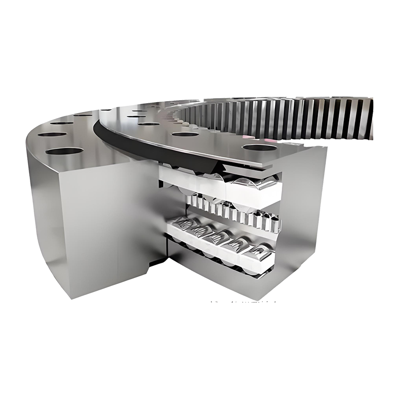
Core Working Principles of a Cross-Roller Slewing Bearing
The operating principle of a single row cross-roller slewing bearing is rooted in the geometry of its roller arrangement and raceway profile. The inner and outer rings each feature a continuous V-shaped groove machined at a 90-degree included angle. Cylindrical rollers with a length-to-diameter ratio close to 1:1 are inserted into this groove in alternating perpendicular orientations, typically separated by spacers or a cage to maintain even spacing and prevent roller-to-roller contact.
When an axial load is applied — for example, the weight of a rotating platform pressing downward — the rollers oriented in one direction transfer that force through line contact against the groove walls to the opposing ring. When a radial load is applied horizontally, the alternating rollers oriented in the perpendicular direction carry that force through their own line contacts. Tilting moments, which arise when an off-center load tries to tip one ring relative to the other, are resisted by the combined effect of rollers on opposite sides of the raceway reacting against their respective groove faces. This three-axis load capacity from a single row is what distinguishes the cross-roller design from all other slewing bearing configurations.
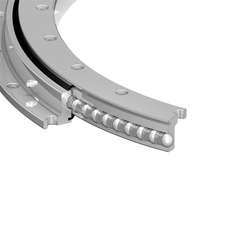
Line Contact vs. Point Contact
The use of cylindrical rollers rather than balls creates line contact between the rolling element and the raceway surface. Line contact distributes the applied load over a significantly larger contact area than the point contact produced by ball bearings. This fundamentally higher stress capacity means cross-roller bearings can carry much greater loads per unit of bearing cross-section than equivalent ball-type slewing rings, while also achieving higher rigidity — an important factor in applications requiring precise positioning under variable loads.
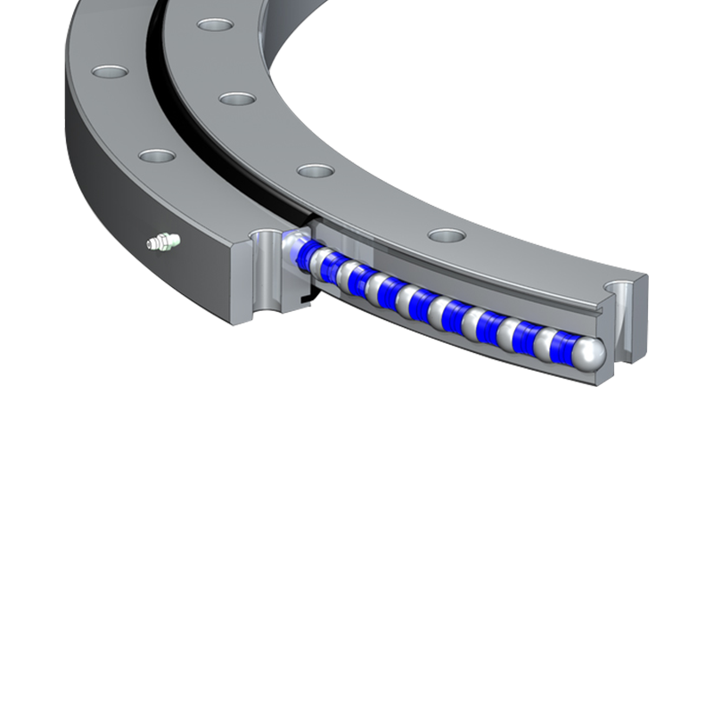
Raceway Preloading and Running Clearance
Many single row cross-roller slewing bearings are manufactured with controlled preload — a slight interference fit between the rollers and the raceway that eliminates internal clearance and increases system stiffness. Preloaded bearings exhibit virtually zero backlash under reversing loads, which is essential in robotic joints, antenna positioning systems, and precision rotary tables. Bearings intended for applications with significant shock loads or thermal cycling may instead be specified with a small positive running clearance to prevent stress buildup from differential thermal expansion between the inner and outer rings.
Main Types of Single Row Cross-Roller Slewing Bearings
Although all single row cross-roller slewing bearings share the fundamental alternating-roller raceway concept, they are manufactured in several distinct structural configurations to serve different installation and load requirements. Understanding these types helps engineers select the most appropriate design for a given application.
Standard Two-Ring Cross-Roller Slewing Bearing
The most common configuration consists of a solid outer ring and a solid inner ring, with the cross-roller assembly running in a single V-groove raceway formed between them. Both rings are typically provided with through-holes or threaded holes on their mounting faces for direct bolting to the machine structure. This type offers a clean, low-profile envelope and is well suited to applications such as rotary tables, indexing stages, and light crane pivots where both rings are fully accessible for fastener installation.
Split Inner Ring Type
In this variant, the inner ring is split into two halves along a plane perpendicular to the bearing axis. This design simplifies roller insertion during manufacturing — rollers and spacers are loaded through the split before the two inner ring halves are assembled and locked together. The split inner ring type allows for a greater roller complement (higher roller fill percentage) than designs that rely on a loading plug hole, which translates to higher load ratings within the same outer envelope. It is commonly found in medium to large diameter slewing rings used in construction equipment turntables and industrial robots.
Split Outer Ring Type
Functionally analogous to the split inner ring design, this configuration divides the outer ring into two halves instead. The split outer ring type is preferred when design constraints make it easier to retain the inner ring as a solid component — for example, when the inner ring serves as the stationary structural base and must maintain its full circular rigidity to resist deformation under heavy tilting moments. The split outer ring halves are precision-ground after splitting and doweled together during final assembly to maintain raceway continuity.
Integrated Gear Type
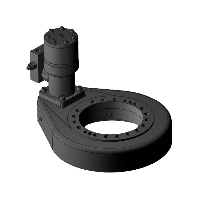
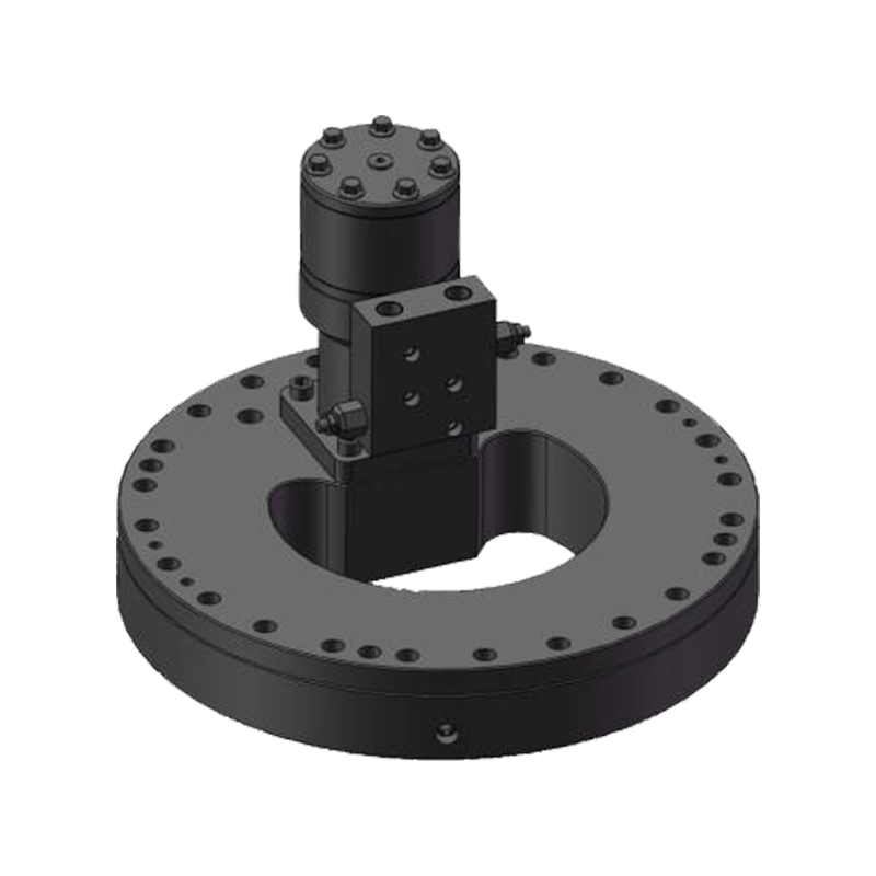
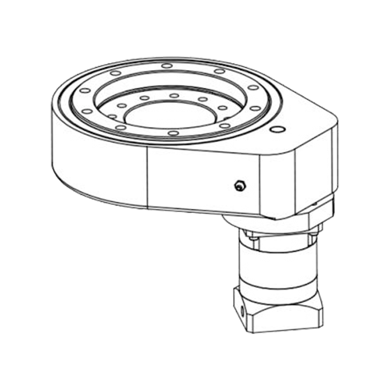
A significant proportion of cross-roller slewing bearings are manufactured with gear teeth machined directly onto the outer diameter of the outer ring or the inner diameter of the inner ring. This integrated gear eliminates the need for a separate ring gear component, reducing assembly complexity and overall system height. External gear versions engage a drive pinion on the outside of the bearing ring, which is the most common arrangement for crane booms, excavator upperstructures, and wind turbine pitch control systems. Internal gear versions place the drive pinion inside the bearing bore, a configuration used where external pinion clearance is restricted by machine geometry.
Key Performance Specifications to Evaluate
Selecting the correct single row cross-roller slewing bearing requires evaluating a set of interrelated performance parameters. The table below summarizes the most critical specifications and their practical significance.
| Specification | Description | Practical Impact |
| Static Load Rating (C0) | Maximum combined load at zero rotation | Determines suitability for hold and lock applications |
| Dynamic Load Rating (C) | Load capacity under continuous rotation | Used to calculate L10 fatigue life |
| Tilting Moment Capacity | Maximum overturning moment the bearing resists | Critical for cantilevered and offset load applications |
| Running Accuracy | Axial and radial runout of the rotating ring | Governs positioning precision in rotary stages |
| Starting Torque | Torque required to initiate rotation from rest | Affects drive motor sizing and energy consumption |
| Gear Module and Tooth Count | Drive gear geometry for integrated gear types | Must match pinion specification for proper meshing |
Lubrication and Maintenance Management
Proper lubrication is the single most important maintenance practice for extending the service life of a single row cross-roller slewing bearing. The alternating roller arrangement and V-groove raceway create contact zones that must be continuously protected by an adequate lubricant film to prevent metal-to-metal contact, corrosion, and fretting damage.
Grease Selection and Initial Fill
Lithium-complex or lithium soap greases with an NLGI Grade 2 consistency are the standard choice for most cross-roller slewing bearing applications operating at low to moderate rotational speeds. For bearings operating in low-temperature environments below -20°C, a synthetic base oil grease with lower pour point characteristics is necessary to prevent lubricant stiffening that would dramatically increase starting torque. High-temperature applications above 120°C continuous operating temperature require polyurea or perfluoropolyether (PFPE) greases resistant to thermal degradation. The bearing should be fully packed with grease at initial installation, with grease fully distributed through the raceway by rotating the bearing slowly through several complete revolutions before final assembly.
Regreasing Intervals and Procedure
Slewing bearings operating under continuous or frequent intermittent rotation require periodic regreasing through dedicated grease nipples or zerk fittings installed in the bearing ring. A general guideline is to regrease every 100 to 200 operating hours under normal conditions, with more frequent intervals in contaminated, wet, or high-temperature environments. During regreasing, the bearing should be rotated slowly to distribute the fresh grease evenly around the full raceway circumference. Excess grease should be allowed to purge through the seals rather than prevented from exiting, as grease purging confirms the raceway is adequately filled and helps flush out contaminated grease.
Seal Inspection and Contamination Control
Single row cross-roller slewing bearings are typically fitted with contact lip seals on both faces of the bearing to retain lubricant and exclude external contaminants. These seals should be inspected at each regreasing interval for cracks, hardening, or distortion. A damaged seal allows abrasive particles, water, or process chemicals to enter the raceway, accelerating wear at a rate that can reduce bearing life by 50% or more compared to a well-sealed assembly. Replacement seals should be sourced from the bearing manufacturer to ensure correct material grade and dimensional fit.
Typical Application Fields
The unique combination of compactness, multi-axis load capacity, and precision makes single row cross-roller slewing bearings the preferred choice across a wide range of demanding industries:
- Industrial Robotics: Joint bearings in articulated robot arms where axial compactness, zero backlash, and high rigidity are required to achieve repeatable positioning accuracy within fractions of a millimeter.
- CNC Rotary Tables: The main pivot bearing in precision indexing and contouring tables for machining centers, where runout must be controlled to micron-level tolerances.
- Medical Imaging Equipment: Gantry rotation bearings in CT scanners and MRI systems, where smooth, vibration-free rotation and non-magnetic material options are critical.
- Satellite Antenna Positioners: Azimuth and elevation drive bearings in tracking antennas and radar systems where moment stiffness directly affects pointing accuracy under wind loading.
- Construction Machinery: Turntable bearings for compact excavators, aerial work platforms, and mini cranes where the combined radial, axial, and tilting loads from the working attachment must be managed within a small structural envelope.
- Semiconductor Manufacturing Equipment: Precision stage bearings in wafer handling and lithography systems where ultra-low running runout and cleanroom-compatible lubrication are mandatory.


Jiangsu Manchen Transmission Technology Co., Ltd. excels in creating custom, reliable, and precise slewing bearings for diverse industries, continuously innovating to meet the highest standards and seeking collaborative opportunities. Reliable and steady slewing bearings supplier in China.
Product links
Contact Us
-
Address:No. 8, Nanqiu Road, Huangtu Town, Jiangyin City,China
-
Tel:+86-13646122221
-
Phone:+86-18796936198
-
WhatsApp:+86 18796936198
-
E-mail:hedy@slewingbearingcn.com
-
E-mail:ma@slewingbearingcn.com
-
E-mail:vena@slewingbearingcn.com
