 English
 русский
 Español
 عربى
عربى

News

Vertical Slewing Drives: Engineering Guide for Buyers & Integrators
 2026.03.19
 Industry news
Content
- 1 What Makes a Slewing Drive "Vertical" — and Why It Matters
- 2 Core Engineering Characteristics
- 3 Industries and Applications
- 4 Load Calculation: What You Must Quantify Before Specifying
- 5 Key Specification Parameters Explained
- 6 Installation Best Practices for Vertical Orientation
- 7 Customization Options We Offer
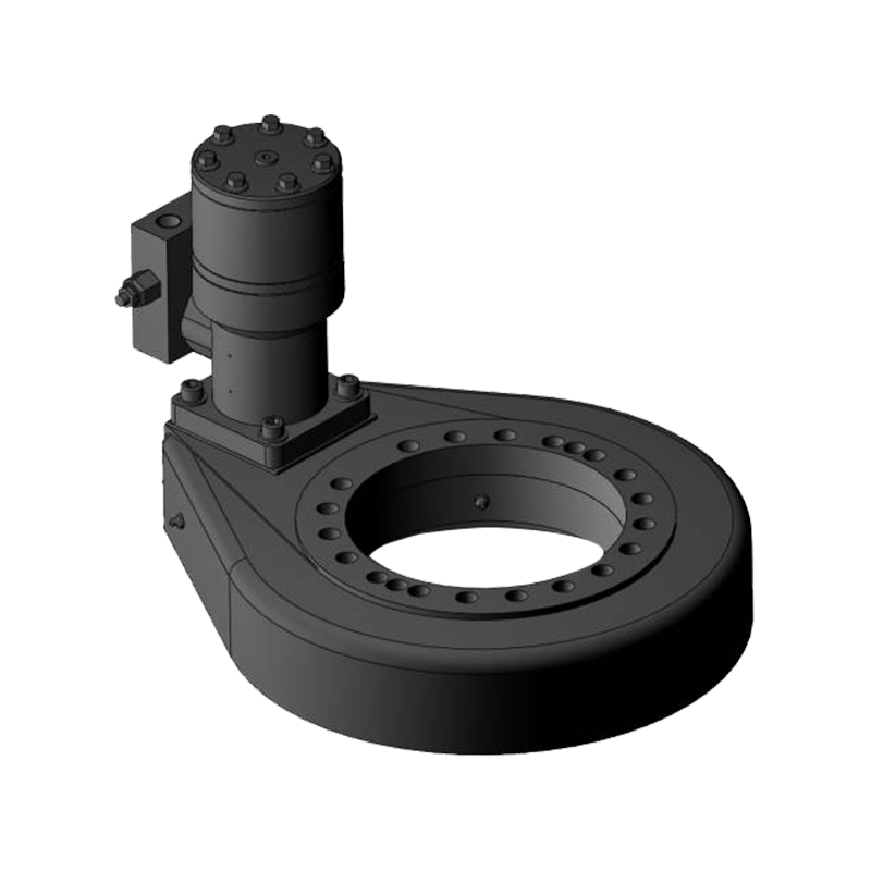
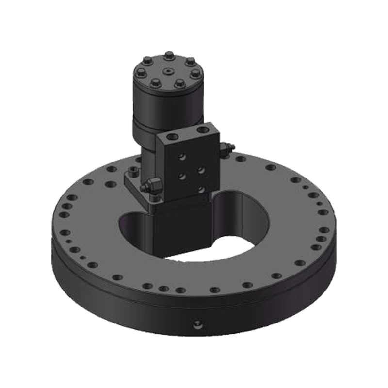
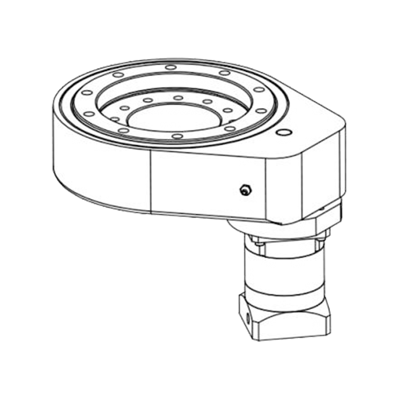
What Makes a Slewing Drive "Vertical" — and Why It Matters
A vertical slewing drive is a fully enclosed worm-gear rotary unit where the output axis is oriented upright — meaning the rotational plane runs parallel to the ground. This distinction is not merely a mounting preference. When a slewing drive operates in vertical orientation, gravity acts directly on the internal components, placing continuous axial and overturning loads on the worm interface and slewing bearing that simply do not exist in horizontal installations.
To handle these gravity-affected forces reliably, vertical slewing drives incorporate structurally reinforced housings, higher-capacity rolling elements, and optimized seal geometries that prevent lubricant migration under sustained downward load. Without these design adaptations, a standard horizontal-orientation slewing drive installed vertically will experience premature gear wear, bearing fatigue, and eventual failure — often within a fraction of its rated service life.
As a manufacturer, we engineer our vertical slewing drives from the ground up for upright operation, not as an afterthought conversion of a horizontal platform.
Core Engineering Characteristics
Understanding the internal architecture of a vertical slewing drive helps buyers specify the correct unit and avoid costly mismatches in the field.
Worm Gear Mechanism and Self-Locking
The worm gear is the heart of any slewing drive. As the motor-driven worm shaft rotates, it transmits torque to the slewing ring's external or internal teeth, producing smooth, high-ratio rotation at the output. The geometry of this engagement means the drive is inherently self-locking: reverse torque from the load cannot back-drive the worm. In vertical applications — solar tracker tilt axes, lifting platforms, tower-mounted antennas — this eliminates the need for a separate mechanical brake to hold position under power loss, simplifying system design and reducing cost.
The hourglass worm profile, where the worm's waist conforms to the curvature of the gear, extends the contact zone to up to 11 simultaneous teeth, distributing load far more effectively than a single-contact conventional worm. This translates directly into higher torque density, reduced contact stress, and extended wear life — a significant advantage in high-cycle vertical applications.
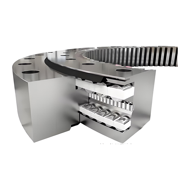
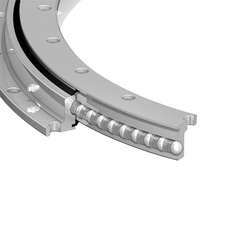
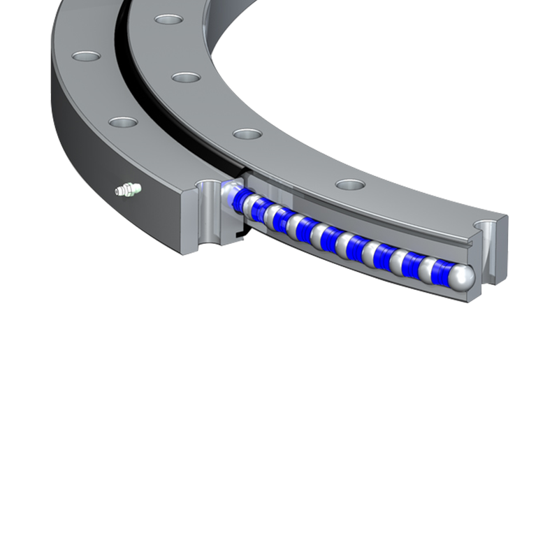
Slewing Bearing Integration
The slewing bearing within the drive simultaneously supports axial loads (the weight of the structure above), radial loads (lateral forces from wind or dynamic motion), and tilting moment loads (eccentric masses). In vertical orientation, the axial load component is dominant and continuous. Four-point contact ball bearings are commonly used in lighter-duty vertical drives; applications with high overturning moments and heavy axial loads frequently demand double-row angular contact or cross-roller configurations to maintain raceway integrity over years of operation.
Sealing and Environmental Protection
Vertical-orientation drives require sealing systems that account for gravity-driven lubricant pooling. Lip seals and labyrinth arrangements are positioned and dimensioned to prevent grease from migrating away from the worm contact zone or leaking from housing joints under the drive's own weight. Standard ingress protection for outdoor vertical drives starts at IP65; marine, offshore, and high-humidity industrial environments typically require IP66 or higher, with salt-fog-resistant coatings applied to exposed ferrous surfaces.
Industries and Applications
Vertical slewing drives appear wherever controlled upright rotation, compact footprint, and load-holding capability are simultaneously required. The following table maps key industries to their typical vertical-drive application and the performance dimension that governs selection.
| Industry | Typical Application | Primary Selection Driver |
|---|---|---|
| Solar Energy | Single-axis horizontal tracker tilt drives | Wind load torque, self-locking, IP rating |
| Construction & Lifting | Aerial work platforms, compact cranes | Axial load capacity, tilting moment |
| Telecommunications | Tower-top directional antennas | Positioning accuracy, corrosion resistance |
| Defense & Surveillance | Radar pedestals, electro-optic turrets | Zero-backlash, shock/vibration resistance |
| Industrial Automation | Robotic arms, rotary indexing tables | Cycle life, gear ratio, compact envelope |
| Marine & Offshore | Deck cranes, mooring systems | IP66+, marine-grade materials |
Solar energy remains the single largest volume application globally. A single-axis solar tracker using a vertical slewing drive can increase energy yield by 25–35% compared to a fixed-tilt installation, making the drive's reliability directly proportional to project revenue over a 25-year system life.
Load Calculation: What You Must Quantify Before Specifying
Incorrect load specification is the leading cause of premature vertical slewing drive failure. Three load components must be calculated independently and then checked against the drive's rated capacities:
- Axial load (Fa): The total downward force acting through the drive's central axis — primarily the weight of the structure, panel, or payload mounted above.
- Radial load (Fr): Lateral forces acting perpendicular to the axis. In outdoor vertical installations, wind pressure is the dominant radial source and must be calculated at the maximum design wind speed for the installation site.
- Tilting moment (Mt): The overturning torque generated by any eccentric mass or asymmetric loading relative to the bearing centerline. This is often the most critical constraint for vertically mounted drives supporting cantilevered structures.
A combined load safety factor of 1.5× to 2× applied to calculated peak loads is standard practice, particularly for outdoor systems subject to variable wind and dynamic operational loads. Provide your engineering team's load data when requesting a quote — this allows us to cross-reference against our rated capacity curves and recommend the right series and size without over-specifying.
Key Specification Parameters Explained
Beyond load ratings, several specification parameters directly govern whether a vertical slewing drive will perform reliably in your application:
- Output torque (Nm): The usable torque delivered at the slewing ring under continuous operation. Distinguish between rated torque and peak holding torque — for self-locking applications, holding torque is often the governing figure.
- Gear ratio: Determines output speed relative to motor input. High-ratio drives (80:1 to 120:1) deliver slow, precise positioning; lower ratios suit applications requiring faster rotation.
- Backlash: The angular free play at the output. Solar tracking and radar applications typically require backlash below 0.1°; general industrial rotation can tolerate higher values.
- Housing material: Standard cast iron suits most industrial environments; marine-grade aluminum reduces weight and improves corrosion resistance for coastal or offshore installations.
- Motor interface: Confirm flange dimensions, shaft diameter, and keyway specification match your motor or hydraulic motor before ordering.
- Lubrication interval: Typical re-greasing intervals range from 3 to 12 months depending on operating cycle frequency, ambient temperature, and contamination exposure.
Installation Best Practices for Vertical Orientation
Even a correctly specified drive will underperform or fail early if installed improperly. The following practices are essential for vertical slewing drive installations:
- Mounting surface perpendicularity: The mating flange must be flat and perpendicular to the drive axis within the tolerance specified in the datasheet — typically ±0.05 mm. Misalignment introduces asymmetric bearing loads that accelerate raceway wear.
- Bolt torque sequence: Use torque-limiting fasteners and a star-pattern tightening sequence to distribute clamp force evenly across the mounting flange. Uneven bolt tension distorts the housing and misaligns the worm-to-ring-gear mesh.
- Commissioning load ramp: Avoid applying full operational load immediately at first start. Run the drive at reduced load for an initial break-in period to allow gear and bearing surfaces to seat correctly without shock.
- Grease verification: Confirm the drive arrives pre-greased to the correct fill level, and establish a documented re-greasing schedule based on actual cycle counts rather than calendar time alone.
- Motor coupling alignment: Verify concentricity and angular alignment of the motor shaft to the worm input. Coupling misalignment generates radial loads on the worm bearings that are not accounted for in the drive's rated capacity.
Customization Options We Offer
Standard catalogue sizes cover the majority of applications, but vertical slewing drives are frequently specified with application-specific modifications. Our engineering team supports the following customization options for our vertical slewing drives:
- Custom bolt-circle patterns to replace existing drives without structural redesign.
- Motor flange adaptation for AC induction, DC brushless, stepper, or hydraulic motor interfaces.
- Gear ratio adjustment within available worm-and-wheel combinations to meet specific output speed requirements.
- Surface treatment upgrades including C5 marine-grade coatings and electrophoretic deposition (ED) for extended corrosion resistance.
- Integrated encoder or limit switch mounting provisions for closed-loop positioning systems.
- Extended IP rating sealing up to IP67 for submersion-risk environments.
For OEM projects or large-volume orders, we engage directly with your design engineers from the specification phase to ensure every dimension, load rating, and interface detail is confirmed before production begins — eliminating costly revision cycles after prototypes are built.


Jiangsu Manchen Transmission Technology Co., Ltd. excels in creating custom, reliable, and precise slewing bearings for diverse industries, continuously innovating to meet the highest standards and seeking collaborative opportunities. Reliable and steady slewing bearings supplier in China.
Product links
Contact Us
-
Address:No. 8, Nanqiu Road, Huangtu Town, Jiangyin City,China
-
Tel:+86-13646122221
-
Phone:+86-18796936198
-
WhatsApp:+86 18796936198
-
E-mail:hedy@slewingbearingcn.com
-
E-mail:ma@slewingbearingcn.com
-
E-mail:vena@slewingbearingcn.com
