 English
 русский
 Español
 عربى
عربى

News

L-Type Single Row Ball Slewing Bearing: Technical Guide and Selection
 2026.03.23
 Industry news
Content
- 1 What Is an L-Type Single Row Ball Slewing Bearing
- 2 Construction and Structural Features
- 3 Load Capacity and Rating Methodology
- 4 Materials and Heat Treatment
- 5 Principal Applications of L-Type Single Row Ball Slewing Bearings
- 6 Comparison with Other Slewing Bearing Types
- 7 Dimensional Designation and Selection Parameters
- 8 Installation, Maintenance, and Service Life
What Is an L-Type Single Row Ball Slewing Bearing
A slewing bearing -- also called a slewing ring or turntable bearing -- is a large-diameter rolling element bearing designed to support simultaneous axial, radial, and moment (tilting) loads while allowing slow rotational motion between two structural components. Unlike standard precision bearings that operate at continuous high speed, slewing bearings are engineered for low-speed, high-load applications where the primary requirement is structural load capacity and reliability across a wide range of combined load directions rather than rotational speed or precision.
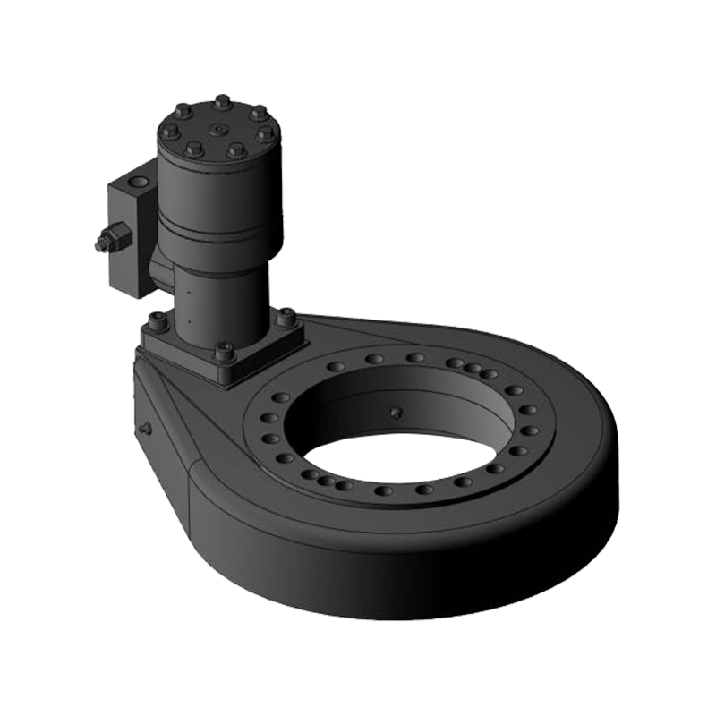
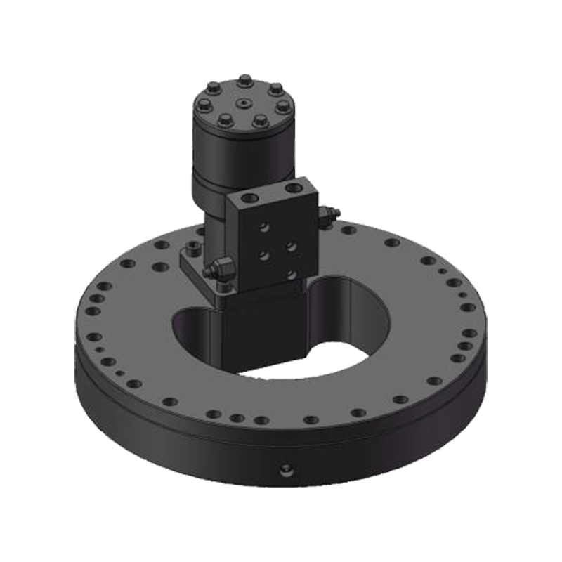
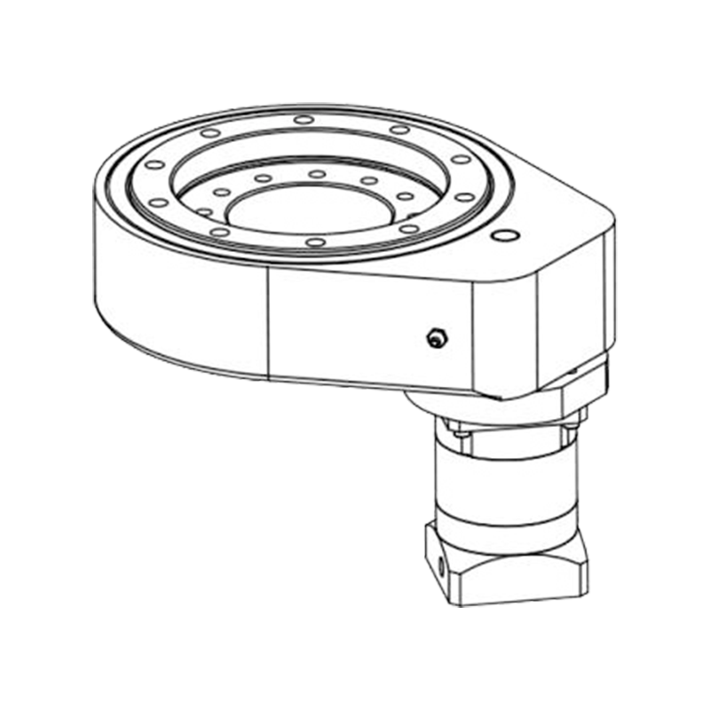
The L-type single row ball slewing bearing is a specific design variant within the slewing ring family. It is defined by two characteristics: its use of a single row of ball rolling elements (as opposed to rollers or multiple rows) and its L-shaped cross-sectional profile, which directly influences the mounting interface, gear tooth positioning, and load distribution characteristics of the bearing. The L-type designation refers to the shape of the inner or outer ring cross-section when viewed in profile -- one ring extends axially in one direction while the other sits flat, forming an L shape that allows the gear teeth and the mounting bolt holes to be located on the same face of the bearing.
This combination of single-row ball construction and L-shaped ring geometry makes the L-type single row ball slewing bearing one of the most commonly specified slewing ring variants in light to medium-duty rotating machinery, where its balance of load capacity, compact axial envelope, and cost-effectiveness across a wide diameter range from 200mm to over 3,000mm gives it broad applicability.
Construction and Structural Features
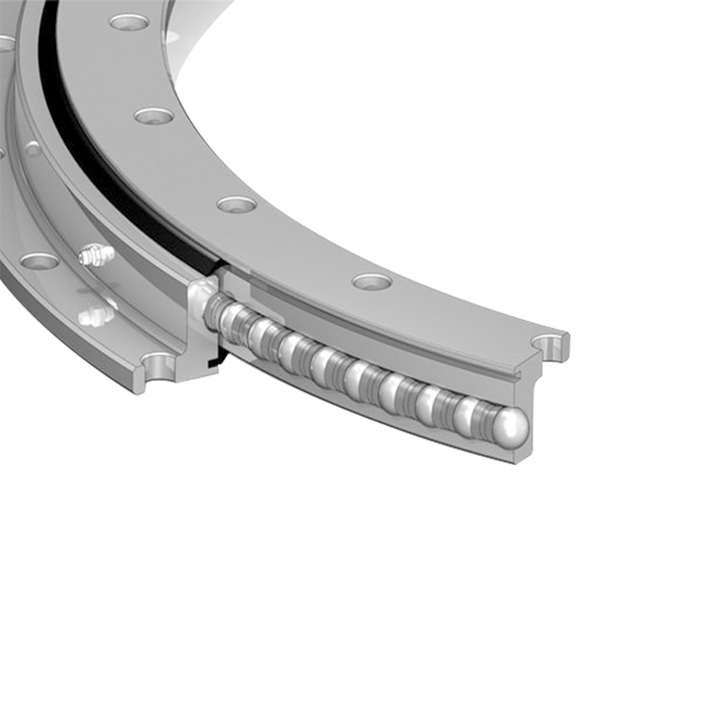
The L-type single row ball slewing bearing consists of an inner ring, an outer ring, a single row of precision steel balls running in machined raceways ground into both rings, a cage or spacer system that maintains ball spacing, and integral gear teeth on either the inner or outer ring perimeter. Each element contributes to the bearing's load-carrying capacity, rotational accuracy, and service life.
The L-Type Ring Profile
The L-shaped cross-section of one or both rings in this bearing type is produced by machining an extended flange on one side of the ring body. This flange serves multiple functions simultaneously. It provides a larger mounting face for attachment bolts, distributing the bolt clamping load over a greater surface area and reducing the risk of deformation of the supporting structure at the bolt holes. It positions the gear tooth profile on the same axial face as the mounting bolt pattern, simplifying the structural design of the slewing drive and driven component. And it stiffens the ring against the tilting moment loads that are characteristically high in crane boom, excavator arm, and aerial platform applications.
The L-profile is most commonly applied to the outer ring, with the extended flange carrying the gear teeth on its outer circumference and the mounting bolt holes on its flat face. The inner ring in this configuration has a simpler rectangular cross-section that mounts to the rotating platform or superstructure. In some designs, the L-profile is on the inner ring, with the gear teeth on the inner diameter and the flange providing the mounting face for the structure that rotates relative to the outer ring. The selection between inner gear and outer gear L-type configurations depends on the drive arrangement and spatial constraints of the specific machine design.
Ball Raceway Design
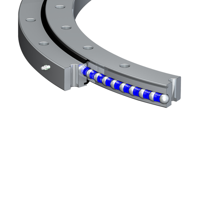
The single row of balls in an L-type slewing bearing runs in gothic arch (four-point contact) raceways ground into both the inner and outer rings. The gothic arch raceway profile -- formed by two circular arc segments of slightly larger radius than the ball, offset to create four contact points between each ball and the raceway -- is a fundamental feature of single-row ball slewing bearings that allows one row of balls to simultaneously carry loads from multiple directions.
The four contact points on each ball are arranged so that two contact the outer ring raceway and two contact the inner ring raceway at positions that resist axial load in both directions (upward and downward), radial load, and the rocking moment that would cause the bearing to tilt. This multi-directional load capacity from a single row of balls is the key engineering feature that makes the single-row ball slewing bearing viable for applications with complex combined loading -- a capability that a simple deep groove ball bearing, with its limited axial load tolerance, cannot provide at equivalent diameter and ring stiffness.
Gear Teeth
The integral gear teeth machined into the perimeter of one ring allow the slewing bearing to be driven in rotation by an external pinion gear, hydraulic motor with a pinion, or electric motor with a gearbox and pinion. The gear teeth in L-type single row ball slewing bearings are most commonly spur gear (straight-cut) teeth, though helical gear teeth are available in larger sizes for applications requiring smoother, quieter drive engagement. Tooth module (the metric measure of tooth size, analogous to diametral pitch in inch measurement) is matched to the drive pinion and selected based on the tangential drive force that must be transmitted at the bearing's pitch diameter.
A significant proportion of L-type single row ball slewing bearings are also produced without gear teeth for applications where rotation is produced by hydraulic cylinders, cables, or external slewing drives mounted separately. Non-geared slewing rings are specified when the drive arrangement does not require an integral gear interface or when the gear is provided on a separate mating component.
Sealing and Lubrication
L-type single row ball slewing bearings are fitted with elastomeric lip seals on both the top and bottom faces of the bearing to retain grease within the raceway zone and exclude contamination. Standard seal materials are acrylonitrile butadiene rubber (NBR) for general applications, and fluoroelastomer (FKM) for elevated temperature or chemical exposure environments. Grease lubrication is supplied through fittings in the inner or outer ring, allowing the raceway to be re-greased in service through the machine's slewing bearing maintenance interval without disassembling the structure.
Load Capacity and Rating Methodology
The load capacity of an L-type single row ball slewing bearing is defined by its ability to withstand the combination of axial force, radial force, and tilting moment that acts on it in a specific application. Unlike standard ball bearings that are rated primarily by their dynamic and static load ratings for a single load direction, slewing bearings are rated using combined load diagrams that show the permissible combinations of axial load, radial load, and moment for a given bearing size.
The Combined Load Diagram
Slewing bearing manufacturers publish combined load capacity diagrams (also called load capacity envelopes or bearing load charts) for each bearing size. These diagrams plot the permissible axial load (vertical axis) against the permissible tilting moment (horizontal axis) for a defined level of radial load, or present the equivalent static load capacity as a curve on a force-moment plot. A load combination that falls within the envelope defined by the bearing's capacity curve is within the bearing's structural capability; a combination that falls outside the envelope will result in raceway contact stress exceeding the allowable level and premature bearing failure.
In practice, the application loads acting on the slewing bearing are calculated from the structural analysis of the machine -- the boom weight, the lifted load, the dynamic load factors for acceleration and braking, and the wind load contribution for outdoor machinery. These calculated loads are then compared against the bearing's combined load diagram to verify adequacy of the selected bearing size.
Static and Dynamic Load Ratings
Because slewing bearings operate at very low rotational speeds -- typically less than 5 rpm in most applications, and often at fractions of one revolution per minute during normal operation -- their service life is not limited by fatigue in the way that high-speed bearings are. The relevant rating for most slewing bearing applications is the static load capacity: the maximum combined load that the bearing can sustain without permanent deformation of the balls or raceways that would impair subsequent smooth rotation.
Dynamic load ratings and L10 life calculations are applied to slewing bearings in applications where significant cumulative rotation occurs over the service life -- for example, in wind turbine pitch bearings that rotate repeatedly through defined blade pitch angles over 20 years of operation. For intermittent-use applications such as mobile cranes and excavators, static capacity verification under the maximum design load combination is the primary sizing criterion.
Raceway Contact Stress and Ball Count
The load capacity of an L-type single row ball slewing bearing is ultimately determined by the Hertzian contact stress at the ball-raceway interface under the design load. This contact stress depends on the ball diameter, the raceway radius ratio (the ratio of the raceway groove radius to the ball radius, which determines the conformity of the contact and therefore its contact area), and the number of balls sharing the applied load. Larger ball diameters and higher ball counts increase load capacity but also increase bearing diameter and mass. The design optimization of an L-type single row ball slewing bearing balances ball size, ball count, raceway geometry, and ring stiffness to achieve the required load capacity within the available dimensional envelope and weight budget of the machine.
Materials and Heat Treatment
The performance and service life of an L-type single row ball slewing bearing are directly determined by the material and heat treatment of the bearing rings and rolling elements. Standard production slewing bearings use specific alloy steel grades for the rings, with surface hardening applied to the raceway zones to achieve the contact fatigue resistance required for the design load and life.
Ring Material
The inner and outer rings of L-type single row ball slewing bearings are most commonly produced from medium carbon alloy steel grades including 42CrMo4 (equivalent to AISI 4140 in the American designation system) and 50Mn (a manganese-alloyed medium carbon steel). These grades combine the core toughness and through-hardening capacity needed for the ring body with the surface hardness response to heat treatment required at the raceway. Some manufacturers use case-hardening steels (such as 18CrNiMo7-6) for specialized applications requiring deep case depth and high core toughness simultaneously.
Raceway Hardening
The raceways in both the inner and outer rings are surface-hardened by induction hardening or flame hardening to achieve a case hardness of HRC 55 to 62 over a case depth of 4 to 8mm, depending on the bearing diameter and ball size. The soft interrupt zones -- deliberately left soft at defined positions around the circumference to prevent cracking during the hardening process and to provide toughness at stress concentration points such as fill plug holes and tooth root areas -- are positioned outside the primary load zone of the raceway. The position and extent of the soft zones relative to the load zone is a critical quality parameter in slewing bearing manufacturing, and their correct placement must be verified during acceptance inspection to ensure that no soft zone falls within the maximum load arc of the application.
Ball Material
The balls in standard L-type single row ball slewing bearings are produced from through-hardened bearing steel, most commonly 100Cr6 (equivalent to AISI 52100), heat treated to HRC 60 to 66. Balls are manufactured to Grade G10 to G40 dimensional tolerance depending on the bearing accuracy class and the raceway clearance specification. Stainless steel balls (AISI 440C or equivalent) are specified for slewing bearings in food processing, pharmaceutical, and marine environments where corrosion resistance of the rolling elements is required.
Principal Applications of L-Type Single Row Ball Slewing Bearings
The L-type single row ball slewing bearing is specified across a wide range of industries and machine types where a rotating connection between two structural components must carry axial, radial, and moment loads while allowing controlled, driven, or free rotation. The following represent the primary application sectors.
Mobile Cranes and Lifting Equipment
The slewing ring is the central structural element of the crane upper structure, connecting the rotating superstructure (boom, counterweight, cab, and hoist mechanism) to the fixed carrier or undercarriage. The L-type configuration is widely used in truck-mounted cranes, pick-and-carry cranes, and knuckle boom cranes where the compact axial envelope of the L-type ring and its integral gear tooth arrangement for the slewing motor drive suit the spatial constraints of vehicle-mounted crane design. The bearing must carry the full rated lifting moment of the crane -- determined by the maximum load multiplied by the maximum outreach -- as the primary design load.
Excavators and Construction Machinery
Hydraulic excavators use a large-diameter slewing bearing to connect the rotating upper structure (cabin, boom, arm, and bucket) to the undercarriage. L-type single row ball slewing bearings are used in compact and medium excavators, where the bearing must carry the combined weight of the upper structure and the digging reaction forces as tilting moment loads while the machine slews to deposit excavated material. The gear teeth on the slewing ring engage the excavator's hydraulic slewing motor pinion, driving the upper structure rotation at the controlled speeds required for precise machine positioning.
Aerial Work Platforms and Cherry Pickers
Aerial work platforms (AWPs), boom lifts, and scissor lifts use slewing bearings to connect the rotating turntable (which carries the boom or scissor mechanism and the working platform) to the machine base. The L-type single row ball slewing bearing is the dominant design in this application because the relatively moderate loads and compact structural proportions of AWPs suit the L-type's capacity range and its ability to integrate the turntable drive gear, the mounting bolt pattern, and the structural connection to the boom base in a single compact component.
Wind Turbines
Wind turbines use slewing bearings in two positions: the yaw bearing (which connects the nacelle to the tower and allows the entire nacelle and rotor assembly to rotate to face the wind direction) and the pitch bearing (which connects each rotor blade to the hub and allows blade pitch angle adjustment). L-type single row ball slewing bearings are used in pitch bearing applications for small to medium wind turbine sizes, where the blade bending moment and centrifugal force combine to produce the complex multi-directional loading characteristic of pitch bearing service. The demanding fatigue life requirements of wind turbine pitch bearings -- 20 years of continuous operation with billions of load cycles across a range of pitch angles and wind conditions -- place the highest demands on raceway hardness consistency, ball and raceway surface finish, and lubricant selection of any slewing bearing application.
Radar, Antenna, and Defense Systems
Radar antenna systems, satellite tracking platforms, and defense vehicle turrets use slewing bearings to support the rotating antenna array or weapon system on a fixed base or vehicle hull. In these applications, bearing rotational accuracy, low friction torque, and long maintenance intervals are the primary selection criteria alongside load capacity. The L-type slewing bearing is used in medium-size antenna and turret installations where its structural rigidity under moment loading and its compatibility with precision drive systems meet the positional accuracy requirements of the tracking or aiming function.
Industrial Rotating Tables and Positioners
Welding positioners, assembly turntables, robotic base platforms, and heavy-duty rotating process equipment use L-type single row ball slewing bearings as the supporting element for the rotating work surface or platform. The integral gear tooth arrangement simplifies the drive design, and the four-point contact ball raceway provides the tilting moment resistance needed when asymmetric loads are placed on the work table or when the positioner tilts the workpiece off-horizontal for welding access.
Comparison with Other Slewing Bearing Types
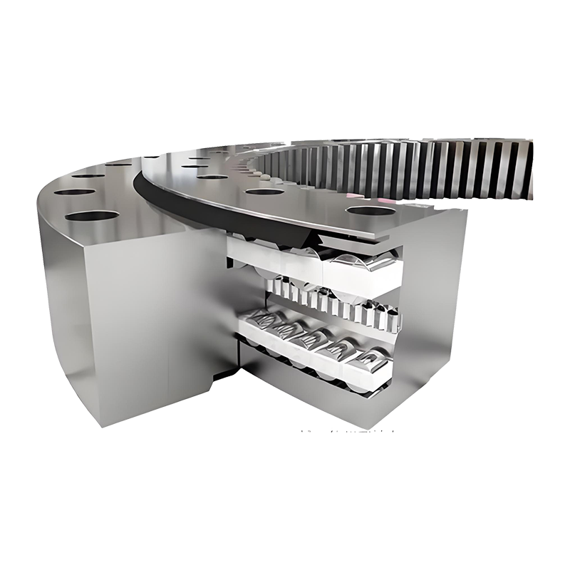
| Parameter | L-Type Single Row Ball | Double Row Ball | Single Row Crossed Roller | Three Row Roller |
|---|---|---|---|---|
| Rolling element | Balls (four-point contact) | Balls (two rows) | Cylindrical rollers (crossed) | Cylindrical rollers (three rows) |
| Load capacity relative to size | Moderate | Higher than single row | High (compact envelope) | Very high |
| Axial height (profile) | Compact | Taller than single row | Compact | Tall (three separate rows) |
| Moment load capacity | Good | Better than single row ball | Very good (high rigidity) | Excellent (dedicated moment row) |
| Rotational accuracy | Moderate | Moderate | High | Moderate |
| Cost relative to capacity | Low to moderate | Moderate | Higher | Highest |
| Typical application scale | Light to medium duty | Medium duty | Precision, medium load | Heavy to very heavy duty |
Dimensional Designation and Selection Parameters
L-type single row ball slewing bearings are designated by a standardized numbering system that encodes the key dimensional and configuration parameters of each bearing size. While designation systems vary between manufacturers, the following parameters are consistently specified in any complete bearing selection.
Key Dimensional Parameters
- Outer diameter (D): The overall outside diameter of the bearing, determining the space envelope required in the machine structure and the mounting bolt circle diameter on the outer ring. Ranges from approximately 200mm to over 3,000mm for commercially available L-type single row ball slewing bearings.
- Inner diameter (d): The bore diameter of the inner ring, which determines the usable interior space through the bearing center (for hydraulic lines, electrical cables, and structural elements that must pass through the slewing axis) and the mounting bolt circle on the inner ring.
- Height (H): The overall axial height of the bearing assembly, which determines the mounting gap between the two mating structures and the available space for seals, lubrication fittings, and the gear tooth profile.
- Ball diameter and number: The ball size and count determine the load capacity of the bearing and are selected by the manufacturer during bearing design. For a given outer diameter, larger balls in a smaller number or smaller balls in a larger number can be used, with different effects on load capacity, ball passing frequency, and minimum rolling speed stability.
- Gear type and module: Whether the bearing is supplied with external gear teeth, internal gear teeth, or no gear teeth, and if geared, the tooth module and the number of teeth, which determines the pitch diameter of the gear ring and the tangential force capacity of the tooth profile.
- Mounting bolt hole pattern: The number, diameter, and pitch circle diameter of the mounting bolt holes in both the inner and outer rings, which must match the bolt pattern of the mating machine structures.
Selection Process
The selection of an appropriate L-type single row ball slewing bearing for a given application follows a defined sequence. The design loads -- maximum axial force, maximum radial force, and maximum tilting moment under all operating and test load cases -- are determined from the structural analysis of the machine. These are compared against the manufacturer's combined load capacity diagram to identify bearing sizes whose capacity envelope includes the design load point with an appropriate safety factor (typically 1.5 to 2.0 on the combined load for standard applications, higher for safety-critical lifting and access equipment).
The selected bearing must also be verified for gear tooth root bending strength and tooth surface contact stress under the maximum drive torque, mounting bolt shear and tension capacity under the design loads, and supporting structure stiffness to ensure that the structure deflections under load do not create edge loading on the ball-raceway contacts. Supporting structure stiffness is a frequently underestimated factor in slewing bearing applications: a rigid slewing bearing mounted on a flexible structure will experience load concentration in the most heavily loaded ball positions that is substantially higher than the load calculated assuming a rigid supporting structure, reducing effective bearing life accordingly.
Installation, Maintenance, and Service Life
Correct installation and regular maintenance are the two factors that most directly determine whether an L-type single row ball slewing bearing achieves its design service life. Premature bearing failures in slewing applications are most frequently attributable to incorrect installation torque on mounting bolts, inadequate or incorrect grease lubrication, contamination ingress through damaged seals, and overloading beyond the design load envelope.
Mounting Bolt Torque
The mounting bolts that attach the inner and outer rings to the supporting structures must be tightened to the specified installation torque using a calibrated torque wrench or torque multiplier. Under-tightening allows relative movement between the ring and the structure under load, causing fretting corrosion of the mating surfaces and fatigue cracking of the bolts. Over-tightening can distort the ring, affecting raceway roundness and causing uneven ball loading. A controlled tightening sequence -- bolts tightened in a diametrically opposite pattern in multiple passes to the full specified torque -- is the standard installation method. Bolt torque should be re-verified after the first 100 hours of operation, as initial bedding-in of the mating surfaces may cause some relaxation of the bolt preload.
Grease Lubrication
L-type single row ball slewing bearings are factory-greased at assembly, and re-greasing intervals are specified by the manufacturer based on the bearing size, operating speed, and environmental conditions. Re-greasing is performed by injecting fresh grease through the lubrication fittings until a small amount of fresh grease extrudes from the seal lips, indicating that the raceway has been fully recharged. The correct grease specification is critical: slewing bearing raceways require a grease with high-viscosity base oil, high load-carrying additives (EP additives), and good adhesion to prevent grease migration away from the loaded zone under the very low rotational speeds typical of slewing bearing operation. Using an incorrect grease -- particularly one formulated for high-speed bearings rather than slow, heavily loaded slewing applications -- is a common cause of premature raceway wear and reduced service life.
Condition Monitoring and Replacement Indicators
The primary indicators that an L-type single row ball slewing bearing is approaching the end of its service life are increased rotational resistance and torque, audible noise during rotation (grinding, rumbling, or irregular clicking), visible axial play (measurable separation between the inner and outer rings under applied axial load), and visible deterioration of the seal condition or lubrication state. Many crane and construction machinery standards require periodic inspection of the slewing bearing play using dial indicators under defined load conditions, with replacement mandatory when the measured play exceeds the manufacturer's maximum permissible value. Gear tooth wear -- visible as increased backlash between the slewing ring gear and the drive pinion -- is a separate wear indicator that can progress independently of the raceway condition and must also be monitored.


Jiangsu Manchen Transmission Technology Co., Ltd. excels in creating custom, reliable, and precise slewing bearings for diverse industries, continuously innovating to meet the highest standards and seeking collaborative opportunities. Reliable and steady slewing bearings supplier in China.
Product links
Contact Us
-
Address:No. 8, Nanqiu Road, Huangtu Town, Jiangyin City,China
-
Tel:+86-13646122221
-
Phone:+86-18796936198
-
WhatsApp:+86 18796936198
-
E-mail:hedy@slewingbearingcn.com
-
E-mail:ma@slewingbearingcn.com
-
E-mail:vena@slewingbearingcn.com
