 English
 русский
 Español
 عربى
عربى

News

Slewing Bearing Guide: Cranes, Excavators & How They Work
 2026.03.11
 Industry news
Slewing is the rotational movement of a structure or load about a vertical axis — the action of swinging a crane boom left or right, or rotating an excavator's upper body relative to its undercarriage. A slewing bearing (also called a slewing ring bearing or turntable bearing) is the large-diameter rolling-element bearing that enables this rotation while simultaneously carrying the combined axial loads, radial loads, and overturning moments generated by the working load above it. In cranes, excavators, and virtually every piece of heavy rotating machinery, the slewing ring bearing is the single component that makes continuous, controlled 360° rotation possible under full working load.
Content
- 1 What Is Slewing: The Mechanics Defined
- 2 How a Slewing Ring Bearing Is Constructed
- 3 Types of Slewing Ring Bearings and Their Applications
- 4 Slewing Bearing in Cranes: Design Requirements and Load Analysis
- 5 Excavator Slewing Ring Bearing: Specific Requirements
- 6 Slewing Bearing Load Rating and Selection Methodology
- 7 Slewing Bearing Maintenance: Extending Service Life
- 8 Major Manufacturers of Slewing Ring Bearings
- 9 Other Applications of Slewing Bearings Beyond Cranes and Excavators
What Is Slewing: The Mechanics Defined
The word "slewing" comes from nautical terminology — originally describing the turning of a ship or its components about a fixed point. In engineering, slewing specifically refers to rotation about a vertical or near-vertical axis, distinguishing it from other rotational motions such as tilting (rotation about a horizontal axis) or rolling. The key characteristic of slewing motion is that it is typically slow, continuous or intermittent, and performed under substantial load — conditions that demand a bearing capable of handling combined loading simultaneously rather than pure axial or radial loading alone.
In a crane, slewing is the rotation of the entire upper structure — boom, hook, counterweight, and cab — around the fixed base or undercarriage. A tower crane may slew continuously through 360° during a lift, rotating to pick up a load on one side of the building and depositing it on the other. In an excavator, slewing rotates the entire upper works (boom, arm, bucket, cab, and engine) relative to the tracked or wheeled undercarriage, allowing the machine to dig in one direction and swing the bucket to a dump truck positioned at any angle without moving the machine itself.
Slewing speed is typically slow by bearing standards — crane upper structures commonly slew at 0.5–3 rpm, and excavator upper works at 8–12 rpm — but the loads involved are enormous. A 100-tonne mobile crane may impose an overturning moment of 5,000–15,000 kNm on its slewing ring bearing at maximum working radius, while simultaneously carrying the axial weight of the entire rotating superstructure.
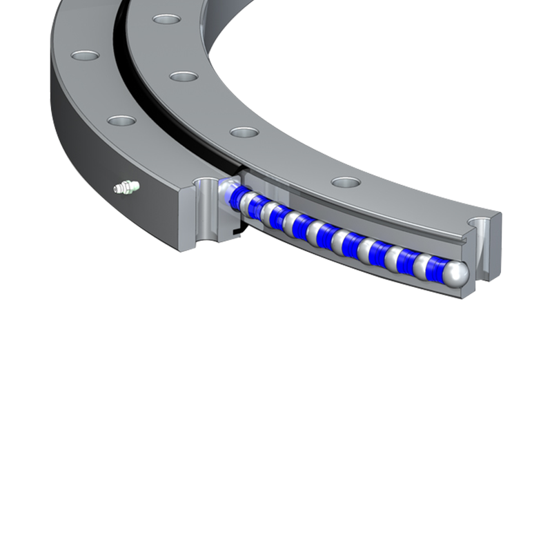
How a Slewing Ring Bearing Is Constructed
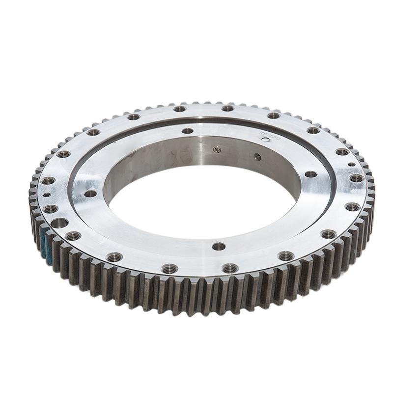
A slewing ring bearing is fundamentally a large-diameter rolling element bearing — typically ranging from 200 mm to over 10,000 mm (10 meters) in outer diameter — designed as an integrated assembly that connects two concentric rings (inner and outer race) through a set of rolling elements arranged around the full circumference. What distinguishes it from a conventional bearing is its combination of large diameter, integrated gear teeth, and its engineered capacity to carry combined loads simultaneously.
Inner and Outer Rings
Both rings are manufactured from medium-carbon alloy steel — typically 42CrMo4 or 50Mn — that is induction-hardened at the raceway surfaces to achieve hardness of 55–62 HRC in the contact zone while leaving the bulk of the ring at a lower hardness for toughness and machinability. The rings are precisely machined with bolt circle holes for attachment to the upper structure (rotating ring) and the lower structure or base (fixed ring). Flange hole diameters range from M16 to M64 depending on bearing size and load class, and the bolt pattern is a primary design parameter — inadequate bolt torquing is a leading cause of premature slewing bearing failure in the field.
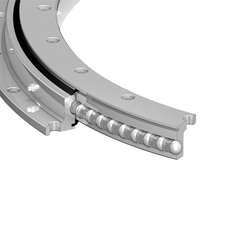
Rolling Elements
The rolling elements transmit load between the rings. Three element types are used in slewing bearings:
- Balls: Provide low friction and good self-alignment tolerance. Used in lighter-duty single-row ball slewing rings and four-point contact ball bearings.
- Cylindrical rollers: Provide high radial and axial load capacity due to line contact versus ball point contact. Used in crossed roller slewing rings and heavy-duty industrial applications.
- Tapered rollers: Provide the highest combined load capacity — axial, radial, and moment simultaneously — due to their geometry. Used in the most demanding crane and excavator slewing rings where overturning moments are extreme.
Integrated Gear Teeth
Most slewing ring bearings incorporate gear teeth machined directly into the inner or outer ring, allowing the bearing to be driven by a pinion gear connected to a hydraulic motor or electric motor mounted on the rotating structure. Gear teeth may be cut on the outer diameter (external gear), the inner diameter (internal gear), or in gearless configurations where a separate drive system is used. Internal gear configurations are most common in excavators and mobile cranes because the pinion is protected within the bearing diameter. Module values for slewing ring gears typically range from Module 4 to Module 30 depending on the torque to be transmitted. Non-toothed (gearless) slewing rings are used in applications where the bearing is driven by friction or where independent drive systems are mounted externally.
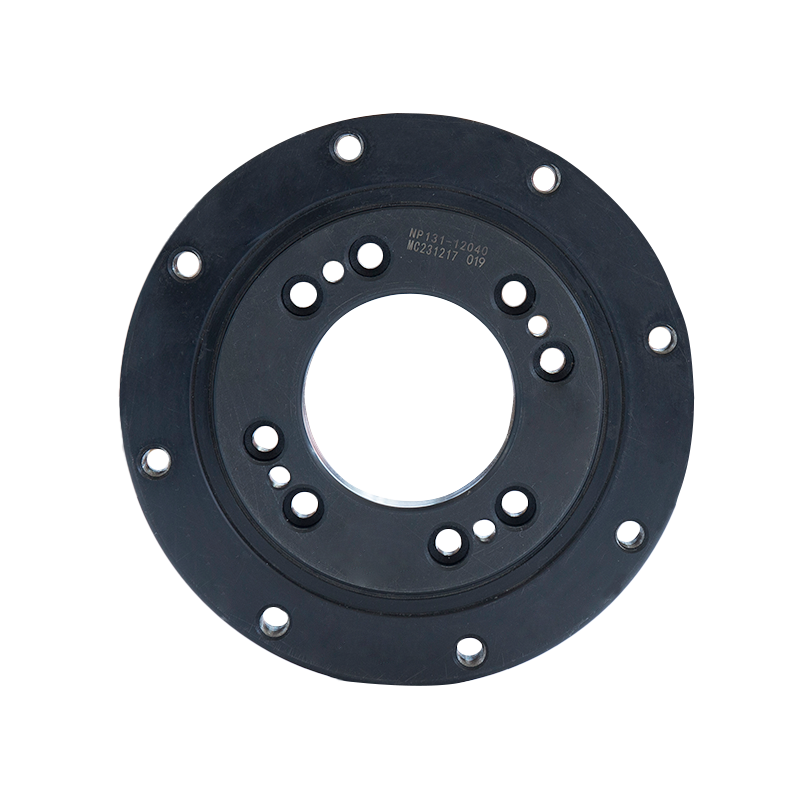
Seals and Lubrication Channels
Slewing bearings operate in environments with significant contamination risk — dust, water, mud, and debris — and require effective sealing to protect the raceway and rolling elements. Integral lip seals (typically NBR rubber or HNBR for higher temperature applications) are fitted into grooves on both inner and outer ring faces, creating a labyrinth that resists ingress. Most bearings also incorporate grease nipples (zerk fittings) at regular intervals around the circumference — typically every 90°–120° — that feed grease directly into the raceway through distribution channels in the ring body. The number of grease points and their spacing is a specification parameter that affects maintenance practicality in the field.
Types of Slewing Ring Bearings and Their Applications
Several distinct slewing bearing configurations are used across different machines and industries. Each has a defined load capacity profile and operational characteristic that determines its suitability.
| Type | Rolling Element | Rows | Load Capacity Profile | Typical Applications |
|---|---|---|---|---|
| Single-Row Four-Point Contact Ball | Balls | 1 | Good axial + moderate radial + moderate moment | Light cranes, aerial platforms, solar trackers, medical equipment |
| Double-Row Ball | Balls | 2 | Higher axial and moment capacity than single-row | Medium cranes, forestry machines, concrete mixers |
| Crossed Roller | Cylindrical rollers (alternating 90°) | 1 | Very high moment capacity relative to section height; compact | Robots, precision tables, radar, small to medium excavators |
| Three-Row Roller (Cylindrical) | Cylindrical rollers | 3 | Very high axial, radial, and moment — each row dedicated to one load type | Large crawler cranes, offshore cranes, heavy excavators, tunnel boring machines |
| Single-Row Tapered Roller | Tapered rollers | 1 | High combined load — axial, radial, and moment in compact profile | Excavators, mobile cranes, material handlers |
| Double-Row Tapered Roller | Tapered rollers | 2 | Maximum combined load capacity in any slewing ring configuration | Large mobile cranes, offshore platforms, heavy port machinery |
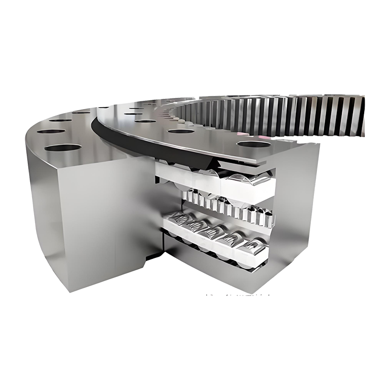
Three-Row Roller Bearings for the Heaviest Applications
The three-row cylindrical roller slewing ring is the engineering solution for the most extreme combined loading conditions. Its design dedicates separate roller rows to each load component: two axial rows (one handling downward axial load, one handling upward axial/moment load) and one radial row. This functional separation means each row is optimized for its specific load type, producing a bearing with substantially higher total load capacity than a single-row equivalent of the same outer diameter. Three-row roller slewing bearings are standard on crawler cranes above 200 tonnes capacity, large offshore pedestal cranes, and bucket-wheel excavators — machines where the slewing ring diameter may exceed 5–8 meters and individual bearing weight exceeds 10,000 kg.
Slewing Bearing in Cranes: Design Requirements and Load Analysis
The slewing bearing crane connection is one of the most mechanically demanding applications for any bearing system. The bearing must simultaneously support the weight of the entire rotating superstructure (including boom, counterweight, cab, hoist machinery, and load), resist the overturning moment generated when a load is suspended at radius from the rotation axis, and accommodate the dynamic shock loads from load pick-up and swing braking.
Understanding Overturning Moment in Crane Slewing Rings
The overturning moment is the dominant load in most crane slewing ring applications. When a crane lifts a load at horizontal distance (radius) R from the rotation axis, the moment arm creates a tilting force that the slewing ring must resist. For a 50-tonne crane lifting its rated load at 10-meter radius, the overturning moment is approximately 50 × 10 × 9.81 = 4,905 kNm from the load alone — before adding the moment from the boom weight and the counteracting moment from the counterweight. The net overturning moment the slewing ring carries depends on the complete structural balance of the crane at each operating radius.
This overturning moment is why crane slewing ring bearings are so much larger in diameter relative to their load class than shaft bearings: a larger bearing diameter creates a longer moment arm between the loaded rolling element rows, which reduces the force on individual rolling elements for a given overturning moment. This is the fundamental geometric reason why bearing diameter increases faster than load capacity requirements in crane slewing ring design.
Tower Crane Slewing Rings
Tower cranes use slewing rings positioned at the top of the mast, where the horizontal jib rotates. The bearing must support the full jib weight (a 60-meter flat-top jib may weigh 15–20 tonnes), the maximum hook load (commonly 6–12 tonnes on standard tower cranes, up to 64 tonnes on high-capacity hammerhead cranes), and the counterweight jib weight — all at varying radii. Tower crane slewing rings are typically single or double-row ball bearings with internal gear teeth, driven by an electric slewing motor through a planetary gearbox. Bearing diameters on standard tower cranes range from 800 mm to 2,500 mm depending on jib capacity and mast section size.
Mobile Crane and All-Terrain Crane Slewing Rings
Mobile cranes — truck-mounted, rough terrain, and all-terrain configurations — use slewing rings that connect the upper rotating superstructure to the carrier chassis. The bearing must handle not only the working loads during lifting but also travel loads when the crane drives with the boom elevated and possibly with a load on the hook (permitted under certain conditions). Mobile crane slewing rings are typically three-row roller or double-row tapered roller configurations for large cranes, sized to match the maximum load moment at minimum working radius. A 250-tonne all-terrain crane may use a slewing ring with outer diameter of 3,000–4,500 mm and a rated static moment capacity exceeding 30,000 kNm.
Excavator Slewing Ring Bearing: Specific Requirements
The excavator slewing ring bearing operates under a fundamentally different load and duty cycle profile compared to crane slewing rings. Where a crane slewing ring may complete only a few rotations per hour during a typical lift operation, an excavator slewing ring may cycle hundreds of full rotations per shift — each cycle involving acceleration from rest, sustained swing at 8–12 rpm, and braking back to rest — with the added complication of significant impact loading from digging and rock-breaking operations.
Load Profile During Excavation
During a typical excavation cycle, the slewing ring experiences at least four distinct loading states:
- Digging phase: The boom and stick are in contact with material. Bucket crowd and breakout forces generate high overturning moments and variable radial forces. On a 20-tonne excavator, breakout force can reach 130–160 kN, generating moment loads transmitted directly through the slewing ring.
- Swing loaded: The upper works rotates with a full bucket. Centrifugal forces add radial loading. Inertia of the loaded boom assembly generates dynamic overturning moment during acceleration and deceleration phases.
- Dump phase: Bucket opens to release load. Sudden reduction in load creates a rebound moment as the structure responds to the change in mass distribution.
- Return swing unloaded: Upper works rotates back to dig position with empty bucket. Lower moment loads but similar dynamic cycling.
This high-cycle, multi-directional load profile means excavator slewing rings are typically designed for fatigue life (L10 life) rather than static capacity alone, and the selection of bearing type reflects this: most excavators use single-row tapered roller or crossed roller slewing rings because their line contact provides better fatigue resistance than ball contact at equivalent cyclic loads.
Excavator Slewing Ring Dimensions by Machine Class
| Machine Class (Operating Weight) | Typical Slewing Ring OD (mm) | Typical Slewing Ring ID (mm) | Common Bearing Type |
|---|---|---|---|
| Mini (1–6 tonnes) | 400–700 | 300–580 | Single-row ball or crossed roller |
| Small (6–15 tonnes) | 700–1,000 | 580–850 | Single-row tapered roller or crossed roller |
| Medium (15–35 tonnes) | 1,000–1,400 | 850–1,150 | Single-row tapered roller with internal gear |
| Large (35–80 tonnes) | 1,400–2,000 | 1,150–1,700 | Single or double-row tapered roller |
| Mining (80–800+ tonnes) | 2,000–5,000+ | 1,700–4,200+ | Three-row cylindrical or double-row tapered roller |
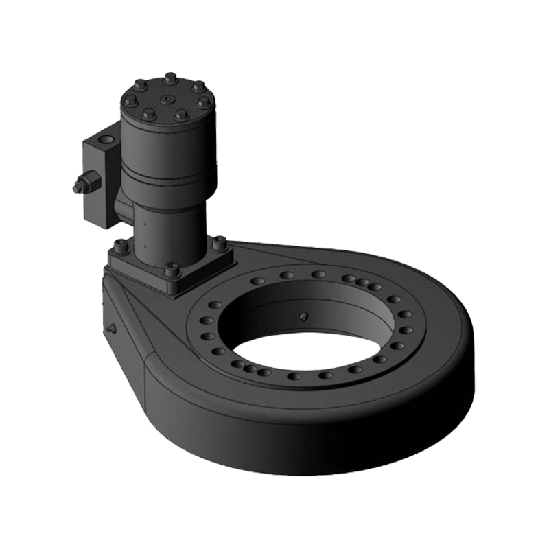
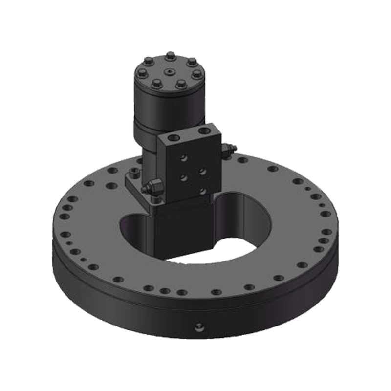
The Slewing Drive System in Excavators
The excavator slewing ring works in conjunction with a dedicated slewing drive — a hydraulic motor connected through a planetary reduction gearbox to a pinion that meshes with the internal gear teeth of the slewing ring. The gear ratio between the pinion and the ring gear is typically 60:1 to 100:1 in the complete drive system (motor, gearbox, and ring gear combined), reducing the hydraulic motor speed (typically 1,500–3,000 rpm) down to the final slewing speed of 8–12 rpm at the upper works. The slewing motor and gearbox are mounted on the upper works, and the reaction force between pinion and ring gear teeth is what drives the rotation — the upper works drives against the fixed ring gear tooth by tooth to produce continuous rotation relative to the undercarriage.
Slewing Bearing Load Rating and Selection Methodology
Selecting a slewing ring bearing requires a different approach to load calculation than standard shaft bearing selection, because the combined loading — axial force (Fa), radial force (Fr), and tilting moment (Mt) — must be converted into an equivalent load that can be compared against the bearing's rated capacity.
Static Load Capacity and Safety Factor
The static load capacity (C0) of a slewing ring is defined as the combined loading condition at which permanent deformation of the rolling element or raceway equals 0.0001 times the rolling element diameter — the threshold at which smooth running begins to be affected. For crane and excavator applications, the static load safety factor (S0 = C0 / equivalent applied load) should be minimum 1.5–2.0 for normal duty and 2.5–4.0 for shock-loaded applications such as digging in rock or impact loading during pile driving attachments.
The Equivalent Load Calculation
Manufacturers provide load diagrams (sometimes called "load capacity charts" or "axial-moment" diagrams) specific to each bearing model that show the permissible combination of axial load and tilting moment for a given radial load. The engineer must calculate the actual Fa, Fr, and Mt from the machine's load cases and verify that this combination falls within the permissible region of the bearing's load diagram. For a first selection, most manufacturers provide a simplified equivalent load formula specific to their bearing series, typically of the form:
Equivalent Static Load = Fa + (4.37 × Mt / D) + (1.5 × Fr)
where D is the bearing pitch circle diameter. The coefficients vary by bearing type and manufacturer — this is an indicative form, and the specific formula from the bearing manufacturer's catalog must be used for actual selection.
Dynamic Load Rating and Fatigue Life
For applications with high duty cycles (excavators, continuous process equipment, port cranes), the dynamic load rating (C) and L10 fatigue life calculation (ISO 76 / ISO 281) are used to verify that the bearing will achieve the required service life before raceway fatigue becomes the failure mode. For excavators, a design life of 10,000–20,000 operating hours (equivalent to 5–10 years at typical utilization) is the standard requirement, though actual life depends heavily on maintenance quality and operating condition severity.
Slewing Bearing Maintenance: Extending Service Life
Slewing ring bearings are expensive components — a replacement bearing for a 50-tonne excavator typically costs $3,000–$8,000, and installation requires specialist equipment and several hours of labor. Planned maintenance is far more cost-effective than reactive replacement and directly determines whether the bearing achieves its design life.
Lubrication: The Most Critical Maintenance Task
The majority of premature slewing bearing failures are attributable to inadequate lubrication — either wrong grease type, insufficient quantity, incorrect interval, or failure to distribute grease around the full circumference. Best practice for slewing ring greasing requires:
- Correct grease specification: Use only the grease type specified by the bearing manufacturer — typically an NLGI 1 or 2 lithium complex or polyurea-based grease with EP (extreme pressure) additives and good adhesion (tackiness) to resist centrifugal throw-out during rotation. Do not mix grease types, as incompatible thickeners can cause grease breakdown.
- Grease while rotating: Apply grease through all nipples while slowly rotating the bearing. Static greasing fills only the section of raceway adjacent to the nipple; rotation distributes grease uniformly around the full circumference. For an excavator, this means completing 2–3 full rotations of the upper works during greasing.
- Correct quantity: Excessive grease is nearly as damaging as insufficient — over-greasing pressurizes the seals, causing lip seal inversion and contamination ingress. Follow manufacturer volume recommendations — typically expressed in grams per lubrication interval per bearing size.
- Interval adherence: Standard maintenance intervals are typically every 250 operating hours for excavators in normal conditions, and every 100–150 hours in dusty, wet, or high-cycle applications. Crane slewing rings may require greasing every 50 operating hours under heavy use.
Gear Tooth Lubrication
The gear teeth on the slewing ring require a separate lubrication program from the raceway. Open gear lubricants — typically heavy-bodied, adhesive bituminous or synthetic open gear greases — are applied to the gear tooth flanks by brush, spray, or automatic lubrication system. Insufficient gear tooth lubrication causes pitting and spalling of tooth flanks, which eventually leads to increased backlash, noise, vibration, and ultimately gear tooth breakage. The pinion gear (the small drive gear meshing with the ring) wears faster than the ring gear and should be inspected and measured for wear at each major service interval.
Bolt Tension Monitoring
Mounting bolt loosening is a common and dangerous failure mode. The slewing ring's attachment bolts must maintain their specified preload throughout the machine's service life. Bolt loosening concentrates bearing load on fewer contact points, accelerates raceway wear, and can lead to bolt fatigue fracture. Bolt tension should be verified with a calibrated torque wrench at every 500 operating hours, and bolts should be replaced at the first sign of elongation, thread damage, or corrosion. The use of Loctite threadlocking compound or prevailing torque nuts on mounting bolts is recommended by many bearing manufacturers for high-vibration applications.
Condition Monitoring: Detecting Deterioration Before Failure
Several practical condition monitoring techniques can identify slewing bearing deterioration before it becomes a catastrophic failure:
- Axial play (clearance) measurement: As raceway wear progresses, the axial clearance between inner and outer ring increases. Most manufacturers specify an initial clearance range and a maximum permissible clearance. Measuring axial play with a dial gauge at regular intervals — typically every 1,000 hours — provides a direct index of remaining bearing life.
- Gear backlash measurement: Increasing backlash between pinion and ring gear indicates tooth wear and provides an indirect measure of bearing race wear. Backlash should be measured and recorded at each major service.
- Grease analysis: Used grease samples extracted from the bearing during greasing can be analyzed for metal particle content (iron, chromium) that indicates raceway or rolling element wear. Increasing particle levels indicate accelerating damage.
- Noise and vibration monitoring: Unusual noise — clicking, grinding, or intermittent rattling during slow rotation — typically indicates raceway damage, rolling element damage, or contamination. Investigation should be immediate as these symptoms indicate damage that will accelerate rapidly.
Major Manufacturers of Slewing Ring Bearings
The slewing ring bearing market is served by a relatively concentrated group of specialist manufacturers alongside the major global bearing companies.
| Manufacturer | Country | Key Product Lines | Notable Strength |
|---|---|---|---|
| Liebherr Components | Germany / Switzerland | Crane and excavator slewing rings | OEM supply to Liebherr cranes; heavy-duty crane bearings |
| Rothe Erde (thyssenkrupp) | Germany | Large-diameter slewing rings, offshore, wind | Very large diameter capability (up to 10+ m); offshore expertise |
| SKF | Sweden | Slewing rings, turntable bearings | Global supply chain; technical support; standardized catalog range |
| IMO (Käpelastik) | Germany | Slewing rings for cranes, solar, medical | Wide standard range; strong in renewable energy applications |
| Xuzhou Wanda Slewing Bearing | China | Excavator and crane slewing rings | Cost-competitive; large catalog; Asian OEM supply |
| Rollix (TPI) | France | Precision slewing rings, medical, robotics | High-precision applications; compact section designs |
Other Applications of Slewing Bearings Beyond Cranes and Excavators
While cranes and excavators represent the highest-profile slewing ring applications, the same bearing technology serves a wide range of other industries wherever large-diameter rotation under combined load is required.
- Wind turbines: Slewing rings are used for both pitch bearings (rotating individual rotor blades about their longitudinal axis to control angle of attack) and yaw bearings (rotating the entire nacelle about the tower axis to face into the wind). A single large wind turbine contains four slewing rings — one yaw bearing and three pitch bearings — each operating in outdoor conditions over a 20+ year service life with limited maintenance access.
- Radar and antenna systems: Precision slewing rings rotate radar arrays, satellite dish antennas, and tracking systems — applications where rotational accuracy, low friction, and backlash control are more critical than absolute load capacity.
- Port and harbor equipment: Ship-to-shore container cranes, harbor mobile cranes, and ship-mounted cranes all use large slewing rings — some of the largest in production at diameters of 6–8 meters for the largest post-Panamax container terminal cranes.
- Mining equipment: Bucket wheel excavators, stacker-reclaimers, and draglines use enormous slewing rings — the bucket wheel excavator's central slewing ring may exceed 10 meters in diameter and weigh over 50 tonnes.
- Medical and industrial robots: Compact crossed roller slewing rings enable precise rotation in CT scanner gantries, surgical robots, and industrial robot shoulder and waist joints, where the combination of compact section height, high moment stiffness, and precise rotational accuracy is critical.
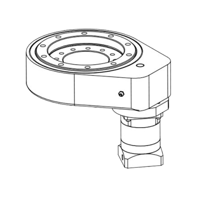
- Solar tracking systems: Single-axis and dual-axis solar tracker systems use slewing rings or slewing drives (integrated bearing, gear, and motor assemblies) to rotate photovoltaic panel arrays toward the sun throughout the day, improving energy yield by 20–40% compared to fixed installations.


Jiangsu Manchen Transmission Technology Co., Ltd. excels in creating custom, reliable, and precise slewing bearings for diverse industries, continuously innovating to meet the highest standards and seeking collaborative opportunities. Reliable and steady slewing bearings supplier in China.
Product links
Contact Us
-
Address:No. 8, Nanqiu Road, Huangtu Town, Jiangyin City,China
-
Tel:+86-13646122221
-
Phone:+86-18796936198
-
WhatsApp:+86 18796936198
-
E-mail:hedy@slewingbearingcn.com
-
E-mail:ma@slewingbearingcn.com
-
E-mail:vena@slewingbearingcn.com
