

 EN
 English
 русский
 Español
 عربى

News
 Home / News / Industry news / Understanding Slew Drive Motors: Torque, Gearing and Real-World Selection
Understanding Slew Drive Motors: Torque, Gearing and Real-World Selection
 2026.11.06
 Industry news
Ask anyone who spends their days around solar fields, port cranes or automated assembly lines what makes a heavy structure swing so smoothly, and the answer is usually the same small component. In our workshop in Jiangyin we have built a great many of these assemblies over the years, and we have noticed that the phrase customers reach for most often is slew drive motor. It is a practical shorthand for a complete motorised rotation unit, where an electric motor, a gearbox and a slewing ring work as one sealed package. This article unpacks what sits inside that package and how to choose one that genuinely fits your machine.
Content
- 1 What a Slew Drive Motor Really Is
- 2 Inside the Assembly: Three Jobs, Three Parts
- 3 Electric Versus Hydraulic: Why the Balance Has Shifted
- 4 Where Motorised Slew Drives Earn Their Keep
- 5 Sizing a Slew Drive Motor: The Numbers That Matter
- 6 Installation and Care That Pays You Back
- 7 Bringing It All Together
What a Slew Drive Motor Really Is
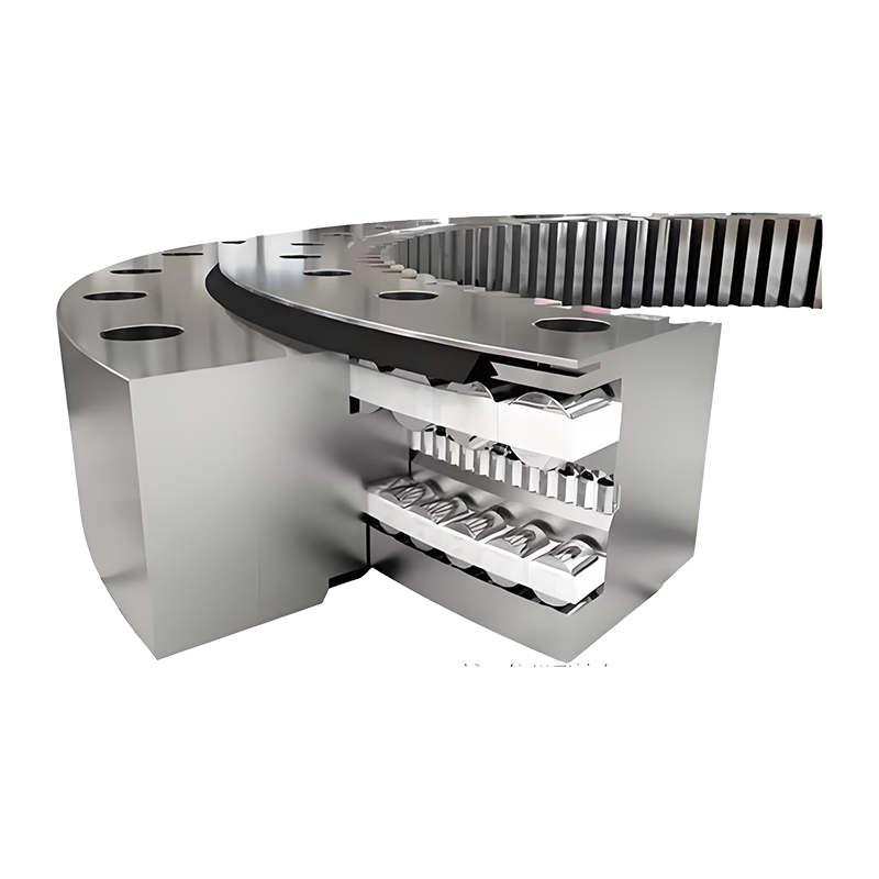
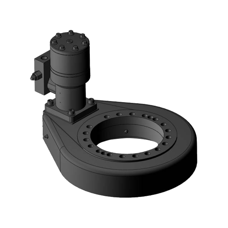
A slew drive is a compact, self-contained gearbox built around a slewing ring bearing. The ring carries the load and provides the large-diameter gear teeth; a hardened worm shaft, supported by the housing, meshes with those teeth and turns the whole assembly. Add a motor to the input shaft and you have a unit that converts a modest amount of electrical power into thousands of newton-metres of rotational torque, at an output speed measured in degrees per second rather than revolutions per minute.
The phrase is used in two slightly different ways, and it is worth being clear about which one you mean. Sometimes it refers to the motor alone, the input component bolted onto a reducer. More often, especially in procurement conversations, it means the complete motorised drive: motor, brake, worm reducer and slewing ring delivered as a single tested unit. Clarifying this early saves a surprising amount of back-and-forth later, because the sizing conversation is quite different in each case. If you would like to see the principle in motion, our note on how a slewing drive enables heavy-duty rotation follows the load path from worm to ring in plain language.
Inside the Assembly: Three Jobs, Three Parts
Every motorised slew drive divides the work between three component groups. Looking at them separately makes it much easier to see where a specification is tight and where there is room to adjust.
The slewing ring carries the load
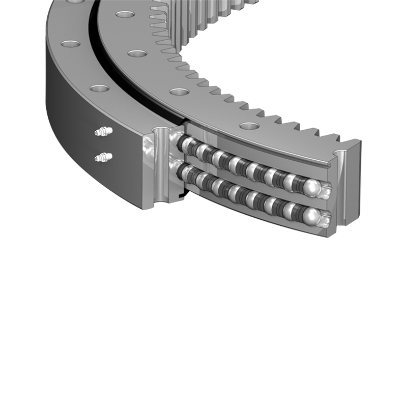
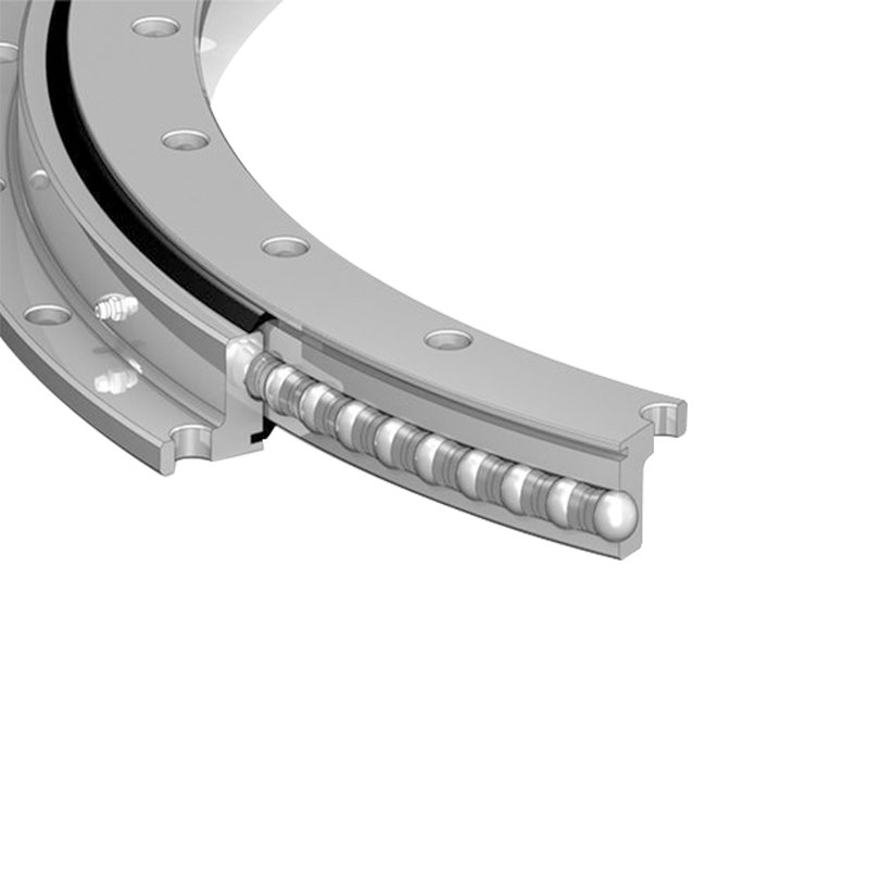
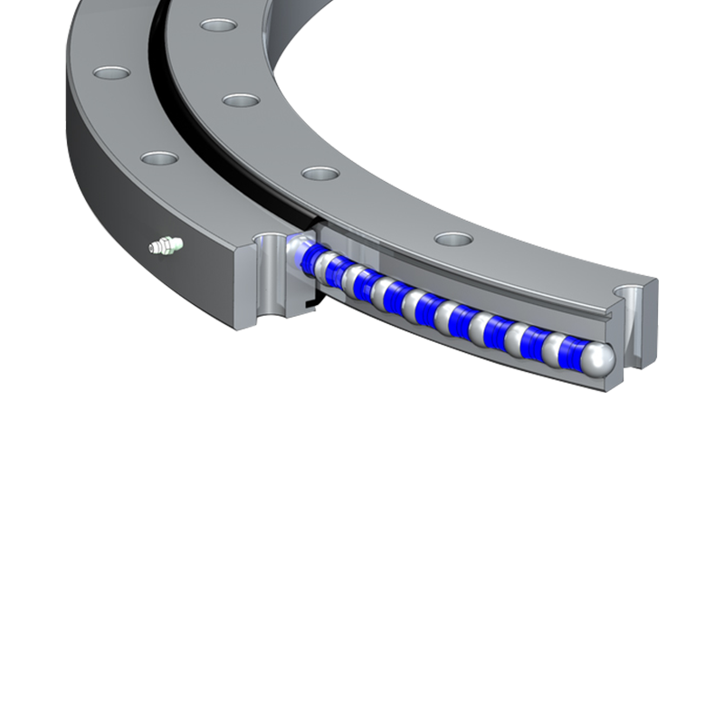
Its raceway takes the axial load, radial load and tilting moment, while the ring of gear teeth around its outside or inside diameter becomes the driven gear. Ring diameter, raceway type and tooth quality largely decide how long the unit stays quiet under load.
The worm set multiplies torque
A high ratio in a very short axial length is the worm drive's great advantage. It also gives a degree of self-locking, which matters on vertical axes where gravity is always willing to help. Housing stiffness and gear finishing determine how much of the calculated torque actually reaches the output without chatter.
The motor sets the character
Stepper, brushed DC, brushless DC or three-phase asynchronous, the motor choice governs controllability, heat, supply requirements and cost. A spring-applied brake and an encoder are usually added at the same interface, which is why it pays to specify them together with the motor rather than afterwards.
Electric Versus Hydraulic: Why the Balance Has Shifted
Hydraulic drives still dominate mobile machinery, and for good reasons: they tolerate shock, they are compact for the torque they deliver, and they are well understood by maintenance teams who already work with them. On fixed installations, though, electric slew drive motors have quietly become the default. Cleanliness, controllability and the absence of a fluid circuit to manage all push the decision in the same direction.
One practical point that comes up again and again: an electric drive holds position with a spring-applied brake that needs no power to stay engaged, which is very welcome in a solar field during a grid outage. A hydraulic motor typically needs sustained pressure or a pilot-operated check valve to do the same job.
| Consideration | Electric drive | Hydraulic drive |
|---|---|---|
| Positioning accuracy | High, with encoder feedback | Moderate, depends on valve control |
| Holding at standstill | Spring brake, no power required | Needs sustained pressure or check valve |
| Routine maintenance | Grease and inspection only | Fluid checks, filters, hoses and seals |
| Cold and hot climates | Consistent available torque | Viscosity changes affect speed |
| Typical fit | Trackers, robotics, medical equipment | Mobile plant, mining, marine decks |
Where Motorised Slew Drives Earn Their Keep
Applications tend to cluster around a handful of pain points: low speed, high torque, outdoor exposure and a requirement to hold position for long periods without drifting.
Solar trackers
A single-axis tracker row moves a few times a day, holds a precise angle, and must survive dust, frost and decades of ultraviolet light. Enclosed housings and generous sealing matter more here than raw speed ever will. Units built for this duty sit in our
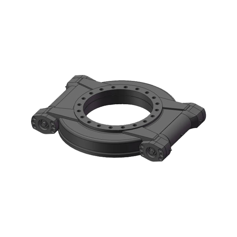 Horizontal Slewing Drives for Single-Axis TrackersSelf-locking horizontal slewing drives provide precise rotary motion for single-axis tracker rows and come in models spanning light to heavy-duty machinery.View Product →
range.
Wind turbine pitch and yaw
Pitch and yaw systems combine high holding torque with demanding safety requirements, and they expect maintenance access to be rare. The worm's self-locking behaviour is a genuine asset on the yaw axis.
Cranes, excavators and lifting equipment
On vertical axes the drive often sits under the machine, driving an internal gear and carrying the weight directly. Strength and alignment dominate the design conversation, and our
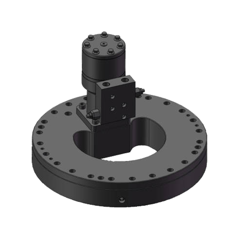 Vertical Internal Gear Slewing DrivesSelf-locking vertical internal gear slewing drives support load-bearing rotation on vertical axes, with internal gear transmission and multiple sizes for industrial machinery.View Product →
designs are frequently specified for this arrangement.
Robotics and compact automation
Here the priorities flip: repeatability, backlash and cable routing through a hollow centre come first. A hollow platform lets wiring pass straight through the rotation axis, which keeps a robot cell tidy and a rotary index table serviceable. Those designs are grouped in
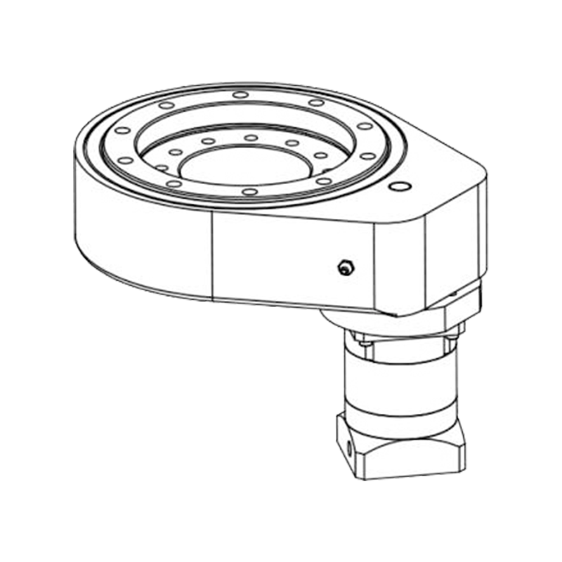 Hollow Rotary Platforms for Precision PositioningHollow rotary platforms allow cables to pass through the rotation axis and provide precise positioning for robotics, rotary indexing and automated equipment.View Product →
.
Medical and special vehicles
Patient positioning tables, mobile lighting masts and aerial work platforms all borrow the same principles: smooth motion, quiet operation and a brake that does not rely on power to stay on.
Sizing a Slew Drive Motor: The Numbers That Matter
Sizing is rarely about picking the biggest unit available. It is about matching torque, geometry and duty honestly, then leaving a sensible safety margin rather than an enormous one.
- Holding torque and dynamic torque: the load when the axis is parked is often the higher number and the one that picks the drive.
- Tilting moment and radial load: check how far the centre of gravity sits from the ring centre, not just the total mass.
- Gear ratio and output speed: think in degrees per second, since most designs never complete a full revolution in service.
- Duty cycle and starts per hour: a tracker that moves twice a day is a completely different duty from a robot joint cycling continuously.
- Environment: dust, salt spray, washdown and ambient temperature drive the sealing, finish and lubrication specification.
- Backlash and repeatability: tight enough to hold a sensor's field of view, loose enough to avoid binding as the structure deflects.
- Brake and manual release: consider how a technician will move the axis during commissioning or after a power loss.
Installation and Care That Pays You Back
The most common causes of early failure we are asked to investigate are not material defects. They are a mounting face that was not flat, bolts that were never re-torqued, or a lubrication interval quietly skipped through a busy season.
- Machine the mounting face flat and clean it thoroughly; a few thousandths of distortion shows up as noise and uneven wear within months.
- Tighten bolts in a cross pattern to the specified preload, using a calibrated wrench rather than judgement.
- Grease the worm mesh and ring gear at the recommended interval, and check the seal lips while you are there.
- Record backlash at commissioning so that later measurements have something meaningful to be compared against.
- Inspect for water ingress after heavy rain or washdown, particularly on vertical installations where water pools on the top face.
Bringing It All Together
A slew drive motor is a small piece of engineering that decides how confidently a large structure moves. Get the torque, the geometry and the duty cycle right, protect it from the weather, and it will quietly do its job for years. If you are working through a selection now, you are welcome to browse our complete slewing bearing and drive range, or simply tell us what your axis has to carry and how often it has to move. That conversation is usually the fastest route to a sensible answer.
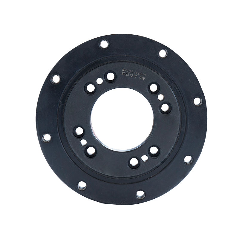

Jiangsu Manchen Transmission Technology Co., Ltd. excels in creating custom, reliable, and precise slewing bearings for diverse industries, continuously innovating to meet the highest standards and seeking collaborative opportunities. Reliable and steady slewing bearings supplier in China.
Product links
Contact Us
-
Address:No. 8, Nanqiu Road, Huangtu Town, Jiangyin City,China
-
Tel:+86-13646122221
-
Phone:+86-18796936198
-
WhatsApp:+86 18796936198
-
E-mail:hedy@slewingbearingcn.com
-
E-mail:ma@slewingbearingcn.com
-
E-mail:vena@slewingbearingcn.com
