

 EN
EN  English
 русский
 Español
 عربى
عربى

News
 Home / News / Industry news / How Do You Select the Right Single Row Cross-Roller Slewing Bearing for Your Application?
 How Do You Select the Right Single Row Cross-Roller Slewing Bearing for Your Application?
 2026.07.22
 Industry news
Content
- 1 Why Crossed Roller Geometry Handles Combined Loads Better Than Ball-Type Designs
- 2 Matching Bearing Selection to Load Direction and Magnitude
- 3 Raceway Hardness and Surface Treatment: A Bigger Factor in Service Life Than Most Buyers Realize
- 4 Sealing Design and Environmental Protection for Harsh Operating Conditions
- 5 Lubrication Intervals and Maintenance Access: Planning for Long-Term Reliability
Why Crossed Roller Geometry Handles Combined Loads Better Than Ball-Type Designs
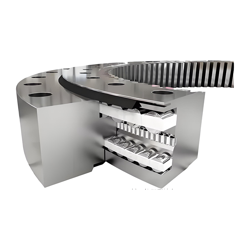
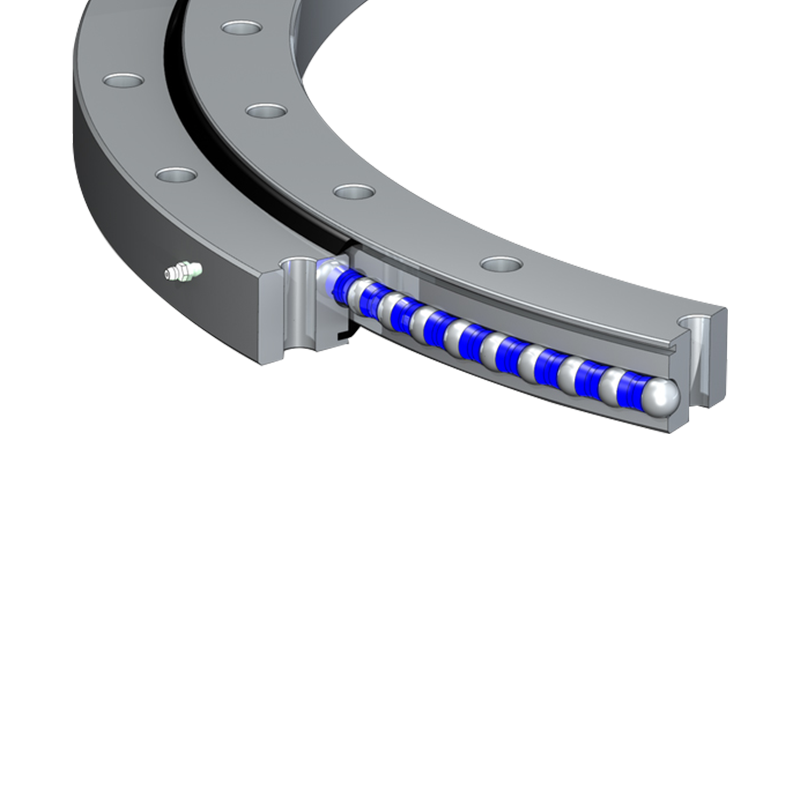
The defining feature of a single row cross-roller slewing bearing is that cylindrical rollers are arranged perpendicular to each other in alternating orientation within a single raceway, rather than running parallel as in most conventional roller bearings. This crossed arrangement means that at any given point around the bearing's circumference, some rollers are oriented to resist axial load while adjacent rollers are oriented to resist radial load, and the alternating pattern also provides moment load resistance — the tipping or overturning force common in cantilevered or off-center loading scenarios. A single row of these crossed rollers can therefore manage all three load types simultaneously within one compact raceway, which is why this design largely replaced the older approach of stacking separate bearings to handle axial, radial, and moment loads independently.
Ball-type slewing bearings, by comparison, distribute load across a smaller contact area between each ball and its raceway, which caps their load capacity at a given bearing diameter. Roller-to-raceway contact in a crossed roller design is a line contact rather than a point contact, spreading load across a larger surface area and allowing a crossed roller bearing to carry substantially higher loads than a ball bearing of equivalent outer diameter — a key reason this design is favored in heavy machinery, wind turbine yaw and pitch systems, and port crane slewing applications where load capacity per unit of installation space matters.
Matching Bearing Selection to Load Direction and Magnitude
Selecting the right size and grade of crossed roller bearing starts with an accurate breakdown of the loads it will actually experience, since underestimating any one load direction — even if the others are well within spec — can lead to premature raceway pitting or roller deformation at that specific load path. Axial load, the force acting parallel to the bearing's rotational axis, is typically the dominant factor in applications like rotary tables or turntables supporting a heavy platform directly overhead. Radial load, acting perpendicular to the axis, becomes more significant in applications like crane slewing rings where lateral forces from boom position and wind loading act on the bearing continuously during operation.
| Load Type | Direction of Force | Common Application Example |
|---|---|---|
| Axial load | Parallel to rotational axis | Rotary tables, platform turntables |
| Radial load | Perpendicular to rotational axis | Crane slewing rings, lateral wind loading |
| Moment load | Tipping/overturning force | Wind turbine pitch and yaw systems, excavator upper structure |
Moment load matters most in applications with an offset center of gravity relative to the bearing's rotational center, such as a wind turbine nacelle or an excavator's upper structure rotating over its tracks — even a load that seems modest in raw weight can generate a large moment load if it's positioned well away from the bearing's central axis, so this calculation shouldn't be simplified down to just the total supported weight.
Raceway Hardness and Surface Treatment: A Bigger Factor in Service Life Than Most Buyers Realize
The raceway surface — the hardened track the rollers travel along — experiences repeated, concentrated contact stress every time the bearing rotates under load, and its hardness and case depth largely determine how long the bearing resists fatigue pitting before performance degrades. Induction hardening is the most common treatment method, typically achieving surface hardness in the 55-62 HRC range while leaving the bearing's core material softer and more ductile, which balances wear resistance at the contact surface against the toughness needed to resist cracking under shock loading.
Raceway specifications worth confirming before ordering
- Surface hardness range (typically 55-62 HRC for induction-hardened raceways)
- Case depth — insufficient depth can allow fatigue cracks to propagate into the softer core material
- Hardness pattern continuity around the full raceway circumference, since gaps at induction hardening overlap points can create localized weak spots
For applications running continuously under high load, such as wind turbine yaw bearings that see millions of load cycles over a service life measured in decades, requesting hardness verification data across multiple points on the raceway circumference — not just a single spot check — gives a more reliable picture of consistent wear resistance around the entire bearing.
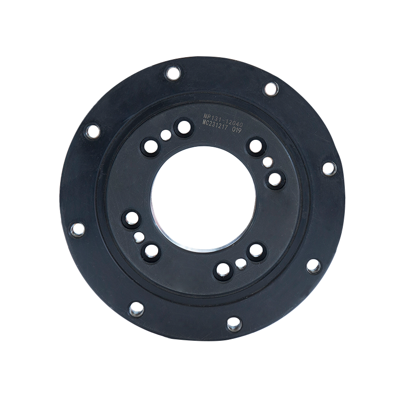
Sealing Design and Environmental Protection for Harsh Operating Conditions
Contamination ingress — dust, moisture, or corrosive particulates entering the raceway — is one of the leading causes of premature slewing bearing failure in outdoor or harsh-environment applications, which makes seal design a critical specification rather than an afterthought. Standard rubber lip seals provide basic protection against dust and light moisture exposure but can degrade faster under sustained UV exposure or in applications with significant temperature swings, where the rubber compound may harden and lose sealing effectiveness over time. Applications in marine, port, or offshore wind environments typically require enhanced sealing systems, sometimes combining a primary lip seal with a secondary labyrinth seal, to resist saltwater spray and airborne corrosive particulates that would otherwise accelerate raceway pitting from contamination working its way into the rolling elements.
Corrosion-resistant coatings on exposed bearing surfaces, separate from the sealing system itself, add another layer of protection specifically for the outer housing and mounting surfaces that remain exposed to the environment regardless of how well the internal raceway is sealed. For bearings operating in consistently high-humidity or coastal environments, specifying both an upgraded seal design and a corrosion-resistant exterior coating addresses two different failure paths rather than relying on one solution to cover both risks.
Lubrication Intervals and Maintenance Access: Planning for Long-Term Reliability
Even a well-selected, properly sealed bearing depends on consistent lubrication to maintain its rated service life, since lubricant film thickness at the roller-raceway contact point is what actually prevents metal-to-metal contact and the accelerated wear that follows. Lubrication intervals vary significantly by operating conditions — a bearing running continuously under moderate load in a stable indoor environment might need re-greasing every few months, while a bearing exposed to heavy contamination, high humidity, or wide temperature swings often requires more frequent intervals to compensate for lubricant degradation or washout.
- Accessible grease fitting placement, positioned for practical access during scheduled maintenance rather than requiring disassembly
- Grease type compatibility with the bearing's operating temperature range and environmental exposure
- Inspection access points for periodic visual or vibration-based condition monitoring without full disassembly
Bearings installed in difficult-to-access locations, such as high up on a wind turbine nacelle or within an enclosed machine housing, benefit significantly from extended-interval lubrication designs or automatic lubrication systems, since the practical cost of a maintenance visit in these settings often outweighs the cost difference between a standard and an extended-interval lubrication design. Planning maintenance accessibility into the bearing selection process, rather than treating it purely as a post-installation logistics issue, generally results in lower total cost of ownership over the equipment's operating life.

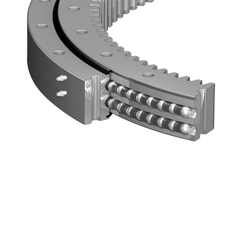
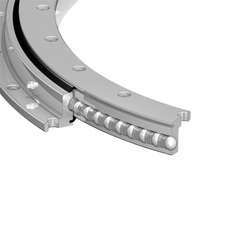

Jiangsu Manchen Transmission Technology Co., Ltd. excels in creating custom, reliable, and precise slewing bearings for diverse industries, continuously innovating to meet the highest standards and seeking collaborative opportunities. Reliable and steady slewing bearings supplier in China.
Product links
Contact Us
-
Address:No. 8, Nanqiu Road, Huangtu Town, Jiangyin City,China
-
Tel:+86-13646122221
-
Phone:+86-18796936198
-
WhatsApp:+86 18796936198
-
E-mail:hedy@slewingbearingcn.com
-
E-mail:ma@slewingbearingcn.com
-
E-mail:vena@slewingbearingcn.com
