 English
 русский
 Español
 عربى
عربى

News
 Home / News / Industry news / What Is the Structure, Components, and Working Principle of a Horizontal Slewing Drive?
 What Is the Structure, Components, and Working Principle of a Horizontal Slewing Drive?
 2026.04.27
 Industry news
Horizontal slewing drives are precision rotary actuator assemblies that combine a slewing ring bearing, a worm gear reduction stage, and a drive housing into a single integrated unit capable of supporting, rotating, and holding loads in the horizontal plane. Unlike conventional rotary gearboxes that transmit torque along a fixed axis, slewing drives manage simultaneous radial loads, axial loads, and overturning moments while delivering controlled rotation — making them the preferred drive solution for applications such as solar trackers, construction cranes, aerial work platforms, industrial robots, satellite antennas, and heavy-duty turntables. Understanding how horizontal slewing drives are built and how they function at a mechanical level is essential for engineers specifying drive systems, maintenance personnel servicing installed equipment, and procurement teams evaluating supplier options.
Content
Overall Structure of a Horizontal Slewing Drive
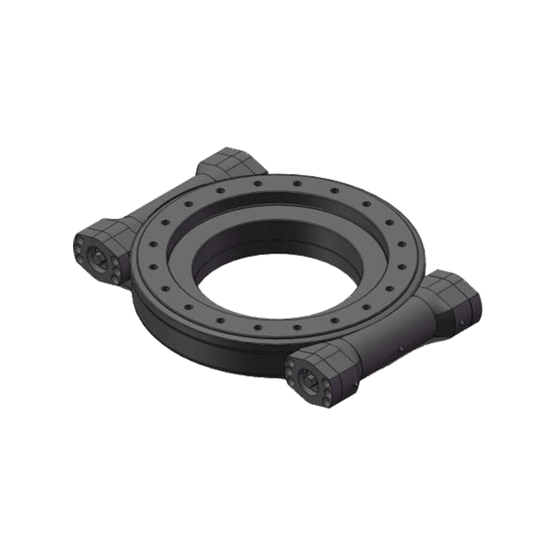
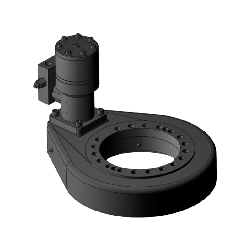
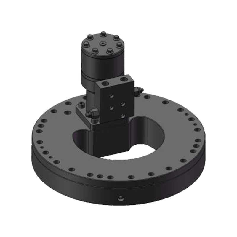
A horizontal slewing drive is a self-contained assembly that integrates the functions of bearing support, gear reduction, and rotational drive into a single compact housing. In the horizontal configuration, the axis of the main slewing ring is oriented vertically — that is, the rotating output table or flange turns around a vertical axis in a horizontal plane, which is the natural orientation for turntables, solar azimuth trackers, and crane slewing systems where the payload rotates horizontally around a vertical center.
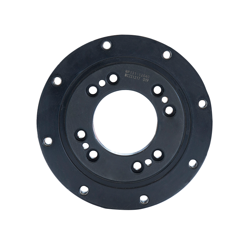
The outer housing of the slewing drive is machined from cast iron or ductile iron and serves as both the structural shell of the gearbox and the mounting interface to the stationary base structure. The housing provides rigidity to resist the significant bending moments generated when off-center loads are applied to the rotating output, and it encloses the gear mesh in a sealed, lubricated environment. Mounting holes on the housing face and base allow bolted connection to the machine frame at standardized bolt circle diameters, and the output flange or ring provides the bolted interface to the rotating load above.
The assembly's overall footprint is compact relative to the loads it manages. A mid-range horizontal slewing drive measuring approximately 300 mm in diameter can typically support axial loads exceeding 50 kN, radial loads above 30 kN, and overturning moments above 15 kN·m while delivering output torques in the range of 5,000 to 20,000 N·m, depending on motor input and gear ratio selection. This power density relative to envelope size is one of the primary engineering advantages that drives adoption of the integrated slewing drive format over separately assembled bearing-and-gearbox solutions.
Core Components and Their Functions
Every horizontal slewing drive is built around a set of core mechanical components that work together to transmit input rotation from a motor into controlled, high-torque output rotation of the slewing ring. Each component serves a specific and irreplaceable function in the load path.
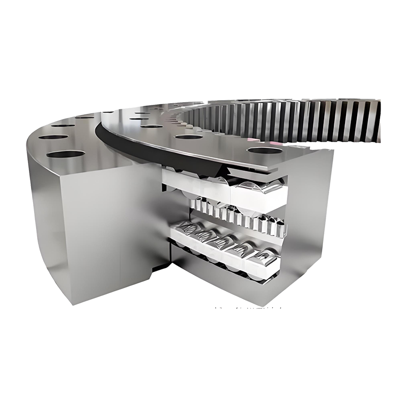
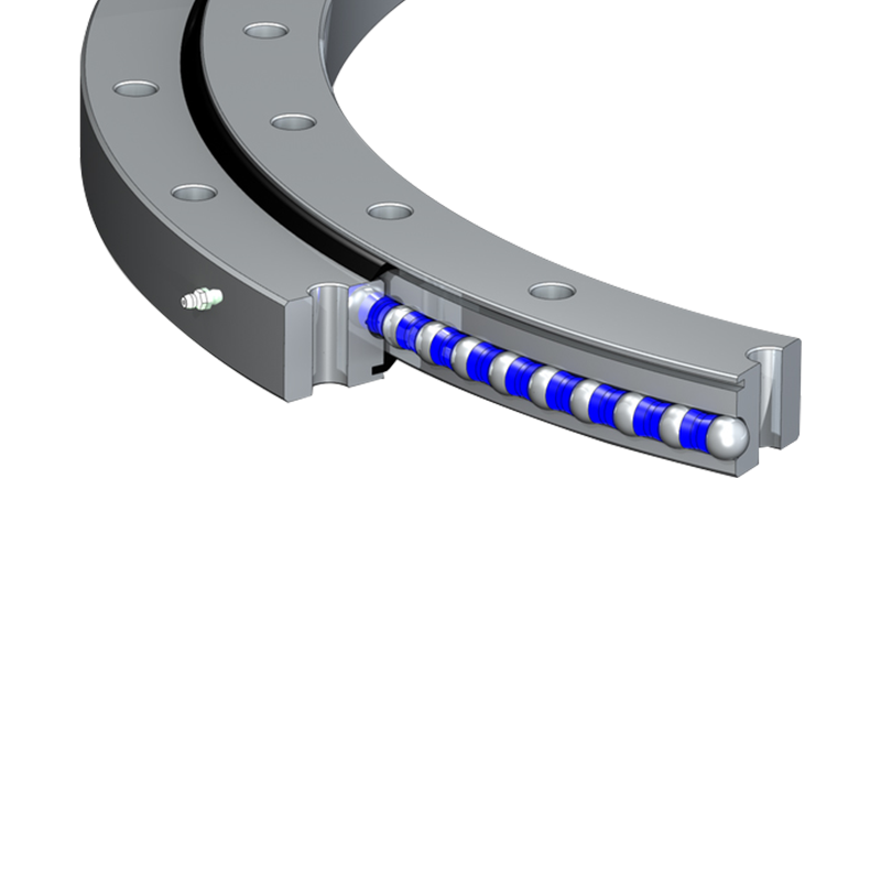
Slewing Ring Bearing
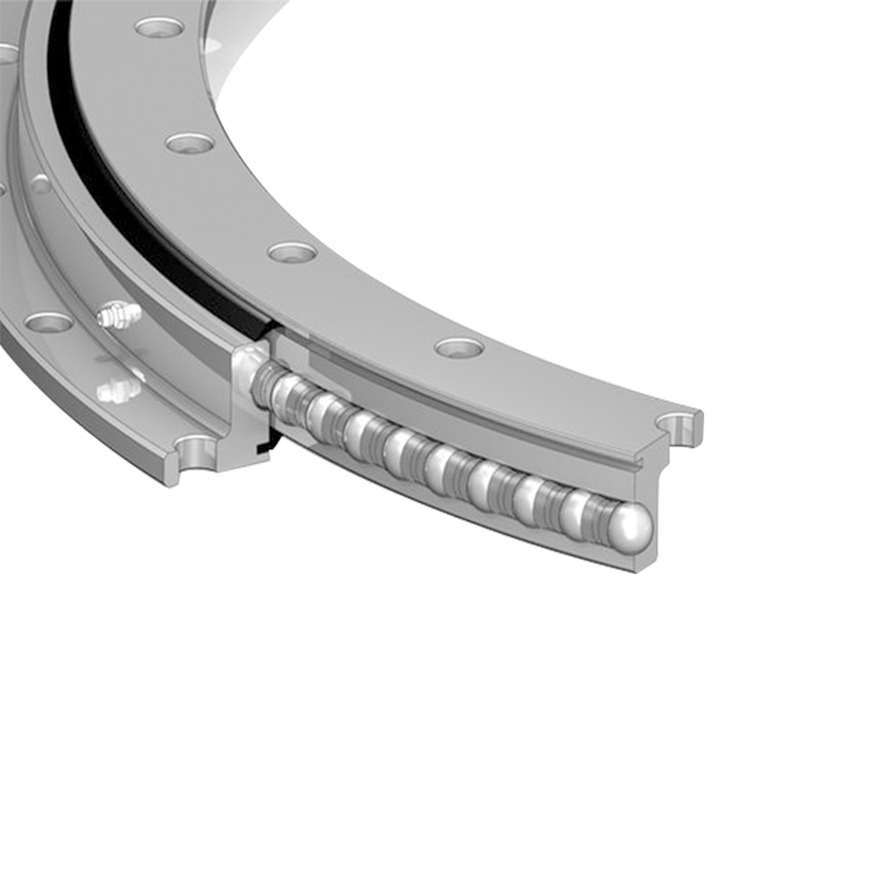
The slewing ring is the central structural component of the assembly. It is a large-diameter rolling element bearing with an integrated gear — typically a worm wheel ring gear — machined into either the inner or outer ring. In horizontal slewing drives, the gear is most commonly machined into the inner surface of the outer ring or the outer surface of the inner ring, depending on the specific design. The rolling elements between the inner and outer rings carry all the applied loads — axial force from the weight of the payload, radial force from horizontal loading, and overturning moment from eccentric loads — while allowing the rings to rotate relative to each other with minimal friction.
Slewing rings in horizontal drives most commonly use single-row four-point contact ball bearings or crossed roller bearings. Four-point contact ball bearings use a gothic arch raceway profile that allows each ball to make contact with the raceway at four points simultaneously, enabling a single row of balls to carry axial loads from both directions, radial loads, and overturning moments. Crossed roller bearings alternate cylindrical rollers at 90-degree orientations in a single row, achieving very high stiffness and moment capacity in a thin cross-section. Both types are used in horizontal slewing drives, with crossed roller designs favored when maximum rigidity and accuracy are required, and four-point contact ball designs favored for cost-effectiveness in heavier but less precision-demanding applications.
Worm Gear Set
The worm gear reduction stage is the mechanism through which motor torque is multiplied and input speed is reduced to the low-speed, high-torque output rotation required by the application. The worm shaft — a helically threaded shaft driven directly by the input motor — meshes with the ring gear teeth on the slewing ring, which functions as the worm wheel in the gear pair. As the worm shaft rotates, the helix angle of the worm thread generates a tangential force on the ring gear teeth, pushing them and the slewing ring around the rotation axis.
Worm gear ratios in slewing drives typically range from 20:1 to 100:1 or higher within a single reduction stage, providing substantial torque multiplication from compact input motor packages. The worm shaft is typically manufactured from case-hardened alloy steel with a ground thread profile to achieve accurate tooth contact and minimize backlash. The ring gear teeth are commonly cut from through-hardened medium carbon steel or, in premium designs, from bronze alloy, which provides favorable friction characteristics against the steel worm and reduces wear on both components.
Worm Shaft Bearings and Housing
The worm shaft is supported at both ends within the housing by rolling element bearings — typically tapered roller bearings or angular contact ball bearings — that carry the radial loads generated by the worm-to-ring gear mesh and the axial thrust forces generated by the helix angle of the worm thread. Proper preload on these shaft bearings is critical for maintaining consistent worm-to-ring gear mesh contact across the full load range of the drive. Inadequate preload allows the worm shaft to deflect under load, increasing backlash and accelerating tooth wear; excessive preload increases bearing friction and heat generation, reducing mechanical efficiency and shortening bearing service life.
Sealing System
Effective sealing is critical to slewing drive service life, particularly in outdoor applications such as solar trackers and mobile cranes where the assembly is exposed to rain, dust, temperature cycling, and UV radiation. Horizontal slewing drives use a combination of labyrinth seals, lip seals, and O-ring face seals at the interface between the rotating ring and the stationary housing, and at the worm shaft entry points into the housing. The slewing ring's rolling element cavity is typically sealed by rubber seals bonded to the bearing rings, preventing lubricant loss and contaminant ingress at the primary bearing interface.
Working Principle: How Rotation and Torque Are Generated
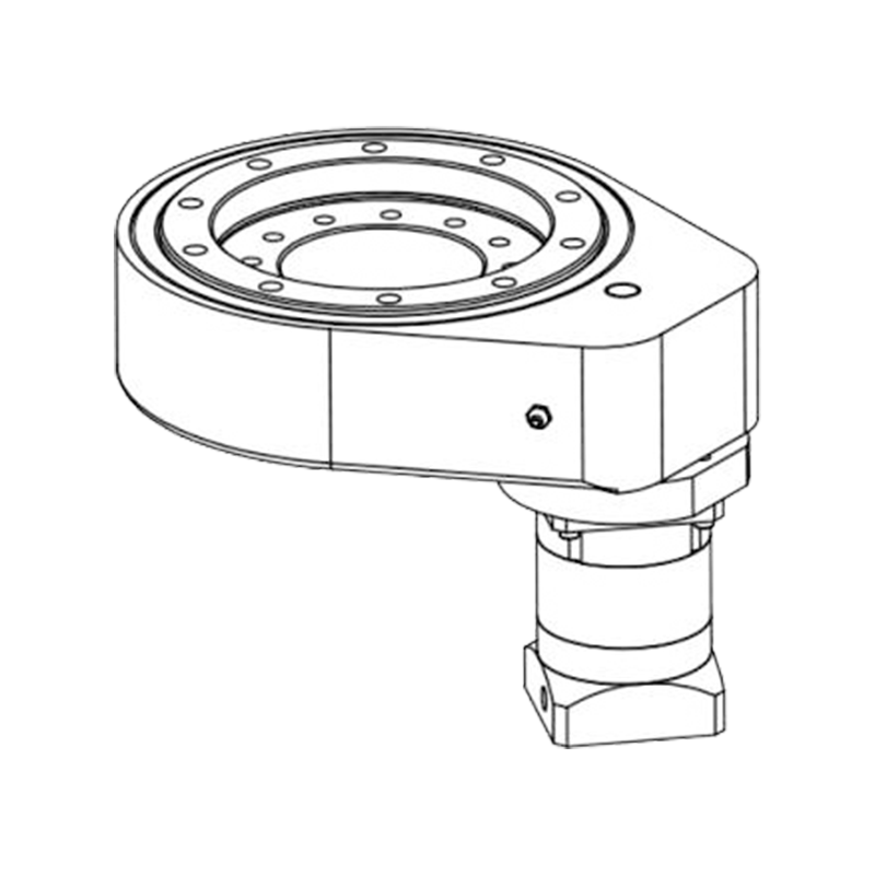
The operating sequence of a horizontal slewing drive begins at the motor — either an electric motor with a planetary gearbox input stage, a hydraulic motor, or in some designs a direct-drive servo motor — which is mounted to the worm shaft input flange of the housing. As the motor shaft rotates, it turns the worm shaft at input speed. The worm shaft's helical thread is in continuous mesh with the ring gear teeth of the slewing ring's inner or outer race.
The geometry of the worm-to-ring gear mesh converts the fast rotational motion of the worm shaft into the slow, high-torque rotation of the slewing ring through a mechanical advantage determined by the gear ratio. If the worm shaft completes one full revolution, the slewing ring advances by a number of ring gear teeth equal to the number of thread starts on the worm. A single-start worm advancing a 60-tooth ring gear produces a 60:1 gear ratio — one full worm revolution moves the ring gear by exactly one tooth pitch, and 60 worm revolutions complete one full rotation of the slewing ring.
The tangential force applied to the ring gear teeth by the worm thread is the product of the input torque multiplied by the gear ratio and the mechanical efficiency of the worm mesh. Worm gears are less mechanically efficient than parallel-axis helical gears due to the sliding contact between worm and wheel teeth rather than the rolling contact of helical gear pairs. Efficiency values for worm-driven slewing drives typically fall in the 50% to 80% range, depending on the lead angle of the worm, the lubrication condition, and the materials used. Higher lead angles (multi-start worms) improve efficiency but reduce the gear ratio per stage; lower lead angles improve the gear ratio but reduce efficiency and increase heat generation at high input speeds.
Self-Locking Behavior
One of the most important functional characteristics of the worm-driven horizontal slewing drive is its inherent self-locking capability. When the worm lead angle is below a threshold value — typically below approximately 6 to 8 degrees, though exact values depend on friction coefficients — the gear mesh geometry prevents the ring gear from back-driving the worm shaft. This means that when motor power is removed, the slewing drive holds its position under load without requiring a separate braking system. The reaction force from the load on the ring gear teeth generates a force component along the worm shaft axis, but friction in the worm-to-wheel contact prevents this force from overcoming static friction and driving the worm to rotate.
Self-locking is a critical safety feature in applications such as solar trackers, aerial work platforms, and material handling equipment where the drive must maintain a fixed position under applied loads during power interruptions or control system failures. It eliminates the need for external holding brakes in many applications, simplifying the system design and reducing component count. However, self-locking slewing drives cannot be back-driven for manual emergency positioning, which must be accounted for in machine safety planning.
Load Capacity Parameters and Selection Specifications
Selecting the correct horizontal slewing drive for a given application requires evaluating four primary load parameters simultaneously, as the slewing ring bearing must support all applied loads concurrently throughout its service life.
| Load Parameter | Definition | Primary Carrying Component | Typical Unit |
|---|---|---|---|
| Axial Load | Force parallel to rotation axis (vertical in horizontal drive) | Slewing ring rolling elements | kN |
| Radial Load | Force perpendicular to rotation axis (horizontal) | Slewing ring rolling elements | kN |
| Overturning Moment | Bending moment from eccentric load or lateral force | Slewing ring bearing couple | kN·m |
| Output Torque | Rotational driving torque delivered to the load | Worm gear mesh and ring gear | N·m |
A critical aspect of slewing drive selection is that these four parameters interact — a drive operating near its rated overturning moment capacity has reduced available axial and radial load capacity, and vice versa. Manufacturer rating tables provide combined load capacity envelopes, and proper selection requires plotting the actual applied load combination against these envelopes rather than comparing individual parameters in isolation.
Lubrication System and Maintenance Requirements
The long-term performance of a horizontal slewing drive is directly determined by the quality and consistency of its lubrication program. Two separate lubrication circuits must be maintained: the slewing ring rolling element circuit and the worm gear mesh circuit, which in most designs share a common oil bath within the housing but may require different lubricant grades in high-performance or extreme-temperature applications.
The worm gear mesh is typically lubricated by oil splash from a reservoir maintained at the bottom of the housing to a level that allows the lower portion of the ring gear teeth to dip into the oil during rotation, carrying lubricant into the mesh contact zone. Recommended lubricants are gear oils with extreme pressure (EP) additives formulated for worm gear applications, with ISO VG 220 or VG 460 viscosity grades being most commonly specified. The high sliding velocity in the worm-to-wheel contact generates heat that must be managed by the lubricant's viscosity-temperature characteristics, and oil change intervals of 2,000 to 4,000 operating hours are typical for drives in outdoor service.
The slewing ring rolling elements require grease lubrication applied through grease nipples located on the ring or housing. The grease must penetrate into the rolling element raceway through grease distribution grooves machined into the ring races. In outdoor installations, regreasing intervals should be aligned with the application's maintenance schedule — typically every 6 to 12 months for solar tracker applications and more frequently for construction equipment exposed to washing and contamination cycles.
Typical Applications of Horizontal Slewing Drives
The design characteristics of horizontal slewing drives — compact integrated construction, self-locking capability, high overturning moment capacity, and controlled low-speed rotation — make them suited to a specific and well-defined range of applications where these properties are required simultaneously.
- Solar photovoltaic trackers: Single-axis azimuth trackers for utility-scale solar farms use horizontal slewing drives to rotate panel arrays around a vertical axis, following the sun's azimuth movement throughout the day. The self-locking characteristic holds panel position accurately during wind loading without continuous motor power, reducing energy consumption and control system complexity significantly.
- Mobile cranes and telescopic handlers: The upper slewing structure of mobile cranes rotates on horizontal slewing drives that must support the full overturning moment of the boom and lifted load while providing smooth, controlled rotation during slewing operations. High overturning moment capacity combined with self-locking load holding are both critical in this application.
- Aerial work platforms (AWPs) and boom lifts: The turntable at the base of the boom assembly rotates on a horizontal slewing drive, supporting the full weight of the extended boom, platform, and occupants as an overturning moment. Compact envelope within the machine base structure is a key requirement that integrated slewing drives satisfy efficiently.
- Industrial positioners and welding turntables: Horizontal slewing drives rotate workpieces around a vertical axis for welding, inspection, or assembly operations, providing precise angular positioning under substantial workpiece weight. The combination of high axial load capacity and accurate positioning from the worm gear mesh makes them well-matched to this application class.
- Satellite communication antennas: Ground-based tracking antennas use horizontal slewing drives for azimuth rotation, where accurate, backlash-minimized positioning is required to maintain antenna beam alignment with moving satellites. Precision-ground worm profiles and preloaded worm shaft bearings are specified in these applications to minimize angular positioning error.


Jiangsu Manchen Transmission Technology Co., Ltd. excels in creating custom, reliable, and precise slewing bearings for diverse industries, continuously innovating to meet the highest standards and seeking collaborative opportunities. Reliable and steady slewing bearings supplier in China.
Product links
Contact Us
-
Address:No. 8, Nanqiu Road, Huangtu Town, Jiangyin City,China
-
Tel:+86-13646122221
-
Phone:+86-18796936198
-
WhatsApp:+86 18796936198
-
E-mail:hedy@slewingbearingcn.com
-
E-mail:ma@slewingbearingcn.com
-
E-mail:vena@slewingbearingcn.com
