 English
 русский
 Español
 عربى
عربى

News
 Home / News / Industry news / What Is the Difference Between a Slewing Bearing and a Crossed Roller Bearing — and Which One Should You Use?
 What Is the Difference Between a Slewing Bearing and a Crossed Roller Bearing — and Which One Should You Use?
 2026.04.22
 Industry news
Content
- 1 Why the Distinction Between These Two Bearing Types Matters
- 2 What Is a Slewing Bearing?
- 3 What Is a Crossed Roller Bearing?
- 4 Structural and Dimensional Differences
- 5 Performance Comparison: Load, Precision, and Speed
- 6 Maintenance, Lubrication, and Service Life Considerations
- 7 How to Choose Between a Slewing Bearing and a Crossed Roller Bearing
Why the Distinction Between These Two Bearing Types Matters
Slewing bearings and crossed roller bearings are both designed to handle combined loads — axial, radial, and moment loads simultaneously — while enabling smooth rotational movement between two components. On the surface, they appear to serve similar functions, and they are sometimes confused in purchasing and engineering decisions. In reality, they occupy quite different positions in the spectrum of rotary bearing solutions, and selecting the wrong type for a given application can result in premature failure, inadequate precision, or unnecessarily high costs.
Understanding the structural, dimensional, and performance differences between slewing bearings and crossed roller bearings is essential for mechanical engineers, procurement specialists, and equipment designers working across industries such as construction machinery, robotics, aerospace, medical devices, and industrial automation. This article breaks down each bearing type in practical terms and provides a direct comparison to support accurate selection decisions.
What Is a Slewing Bearing?
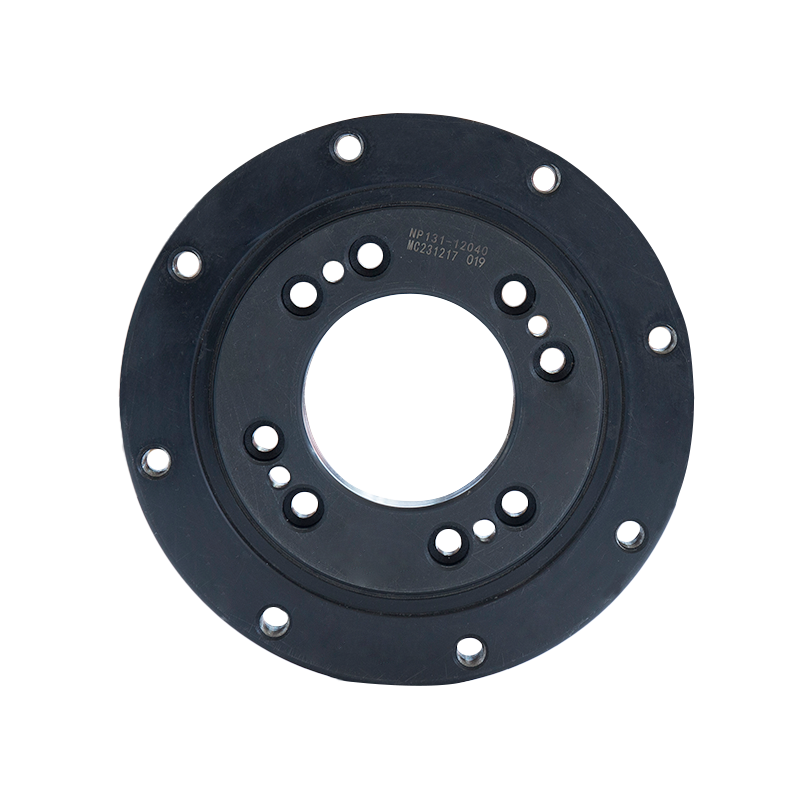
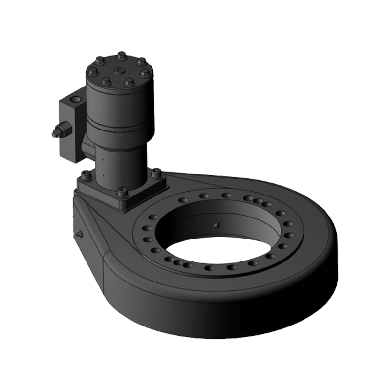
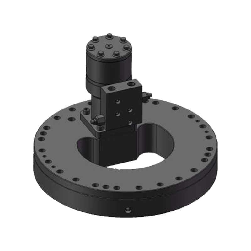
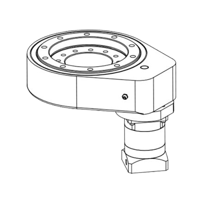
A slewing bearing — also called a slewing ring bearing or turntable bearing — is a large-diameter rotary bearing designed to support heavy combined loads at relatively low rotational speeds. It consists of an inner ring and an outer ring, one or both of which typically feature mounting holes for direct bolting to structural components. Between the rings, rolling elements — which may be balls, cylindrical rollers, or crossed rollers depending on the design variant — transmit the applied loads.
Slewing bearings are defined primarily by their large size and structural integration. Diameters commonly range from 200 mm to over 4,000 mm, and they are frequently machined with gear teeth on the inner or outer ring to allow direct drive by a pinion gear. This built-in drive capability is one of the most distinctive features of slewing bearings and sets them apart from virtually all other bearing types. The gear can be spur-cut or helical, and the tooth profile is matched to the drive system of the specific machine.
Common applications include crane booms, excavator upper structures, wind turbine pitch and yaw systems, industrial robots with heavy payloads, radar antenna mounts, and offshore drilling turntables. In all these cases, the bearing must withstand very high loads — often tens or hundreds of tonnes — while rotating slowly and maintaining structural alignment between large connected components.
What Is a Crossed Roller Bearing?
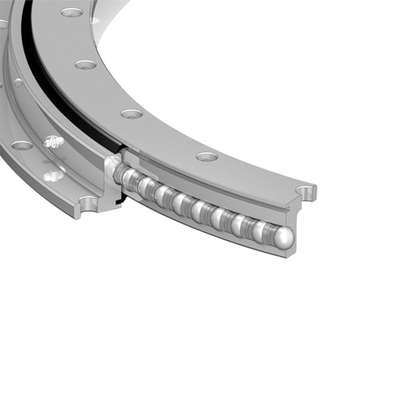
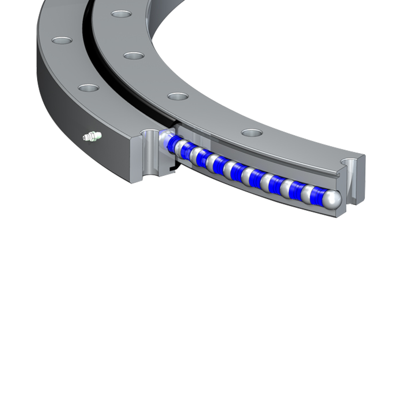
A crossed roller bearing is a compact, high-precision rotary bearing in which cylindrical rollers are arranged alternately at 90° angles to each other within a single raceway. This crossed arrangement — with adjacent rollers oriented perpendicularly — allows a single bearing to carry axial loads, radial loads, and moment loads simultaneously with exceptional rigidity and minimal deflection. The V-shaped grooved raceway machined into both the inner and outer rings provides the contact geometry that makes this load distribution possible.
Crossed roller bearings are defined by their precision and compactness. They are manufactured to tight dimensional tolerances — often P5 or P4 class under ISO standards — and are available in configurations with a split inner ring, split outer ring, or in a wire race construction for particularly thin-section applications. Outer diameters typically range from around 20 mm to 1,000 mm, though the vast majority of applications use sizes below 400 mm. Thin-section crossed roller bearings with very small cross-sectional height-to-diameter ratios are a particularly important subcategory used in robotics and semiconductor equipment.
Typical applications include industrial robot joints and wrist axes, rotary tables for CNC machining centres, medical imaging equipment (CT scanners, surgical robots), semiconductor wafer handling systems, optical instruments, and precision measurement devices. In these contexts, the priority is not raw load capacity but positional accuracy, tilt rigidity, and smooth low-speed motion.
Structural and Dimensional Differences
The most immediately apparent difference between these two bearing types is physical scale and construction philosophy. Slewing bearings are large structural components that become load-bearing joints in the machines they are installed in. Crossed roller bearings are precision components integrated into mechanisms where compactness and accuracy are the primary design constraints.
Rolling Element Arrangement
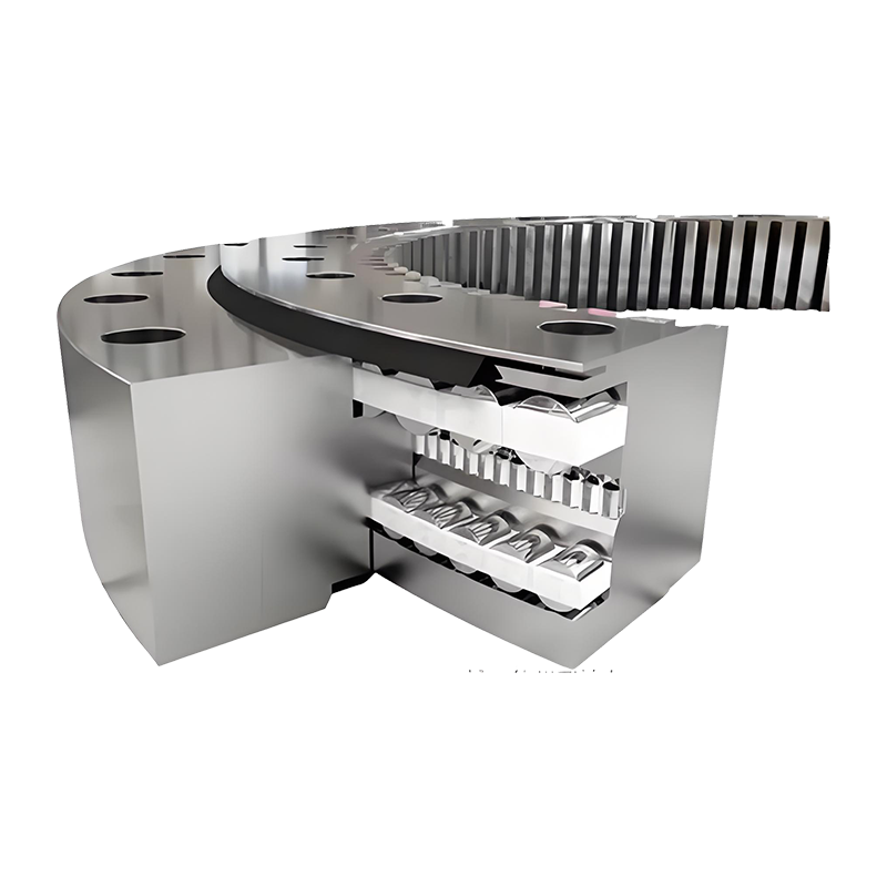
In a standard single-row ball slewing bearing, balls roll within a single circular raceway and can accommodate loads in multiple directions, but with lower moment rigidity compared to roller-based designs. Four-point contact ball slewing bearings use a gothic arch raceway profile to achieve contact at four points per ball, improving moment capacity while retaining the relative simplicity of ball construction. Roller slewing bearings use cylindrical rollers arranged in one or more rows to handle higher radial and axial loads with greater surface contact.
In a crossed roller bearing, every roller is a precision-ground cylinder, and adjacent rollers are oriented at exactly 90° to each other. This alternating arrangement means that half the rollers carry axial load in one direction, the other half carry axial load in the opposite direction, and all rollers share radial load — all within a single compact ring assembly. The result is a bearing with exceptional stiffness in all load directions despite a very small cross-sectional profile.
Integration with Drive Systems
Slewing bearings are routinely supplied with integral gear teeth, enabling direct coupling to a drive pinion. This is a fundamental design feature that simplifies machine architecture — the bearing simultaneously provides the rotary joint and the power transmission interface. Crossed roller bearings do not incorporate gear teeth and require separate drive arrangements (such as harmonic drives, belt drives, or external ring gears) when rotation must be actuated rather than free-wheeling.
Performance Comparison: Load, Precision, and Speed
The performance characteristics of these two bearing types reflect their different design priorities. The table below summarises the most critical comparison points:
| Parameter | Slewing Bearing | Crossed Roller Bearing |
|---|---|---|
| Typical Diameter Range | 200 mm – 4,000+ mm | 20 mm – 1,000 mm |
| Load Capacity | Very High (tonnes range) | Medium (kg to low-tonne range) |
| Rotational Precision | Moderate | Very High (P5/P4 class) |
| Moment Rigidity | High (roller type) | Very High per unit size |
| Operating Speed | Low (typically <10 rpm) | Low to Medium (<100 rpm typical) |
| Gear Integration | Yes (standard option) | No |
| Cross-Section Profile | Large, structural | Compact, thin-section available |
| Typical Applications | Cranes, excavators, wind turbines | Robots, CNC tables, medical devices |
Load Capacity
Slewing bearings are purpose-built for extreme loads. A large-diameter roller slewing bearing used in a port crane can carry axial loads exceeding 500 tonnes and moment loads in the range of several thousand kilonewton-metres. This capacity is a product of both the large rolling element contact area and the large diameter of the bearing itself, which creates a long moment arm that amplifies resistance to tilting forces. Crossed roller bearings, by contrast, are optimised for precision in compact spaces — a 200 mm outer diameter crossed roller bearing might carry axial loads in the range of 5 to 15 kN and moment loads of 1 to 3 kNm, which is adequate for a robot joint but wholly inadequate for construction machinery.
Rotational Accuracy and Runout
Crossed roller bearings are precision components manufactured to extremely tight tolerances. Radial runout values of 3 to 5 micrometres and axial runout values of the same order are achievable in standard P5-class crossed roller bearings. This level of accuracy is essential in applications like CNC rotary tables, where positional repeatability directly affects machined part quality, or robotic wrist joints, where cumulative angular error across multiple axes determines end-effector positioning accuracy. Slewing bearings are not manufactured to these tolerances — their dimensional accuracy is sufficient for structural alignment but not for precision motion control applications.
Maintenance, Lubrication, and Service Life Considerations
Maintenance requirements differ substantially between the two bearing types, reflecting the different operating environments and criticality levels of their respective applications.
Slewing bearings operating in outdoor or harsh environments — construction sites, offshore platforms, wind farms — require regular greasing through fittings distributed around the circumference of the bearing. The large rolling element path means grease must be distributed by rotating the bearing during re-lubrication to ensure full coverage. Seal condition should be inspected periodically, as contamination ingress through damaged seals rapidly accelerates raceway wear. Many slewing bearing failures in service are attributable to inadequate or incorrect lubrication rather than overloading.
Crossed roller bearings used in cleanroom or precision environments are often supplied pre-greased and sealed for life, requiring no field maintenance. In applications where re-lubrication is performed, the small quantities of grease involved and the tight tolerances of the bearing mean that over-greasing can be just as damaging as under-greasing — excess grease increases running torque and can cause thermal issues at higher speeds.
How to Choose Between a Slewing Bearing and a Crossed Roller Bearing
The selection decision becomes straightforward once the application requirements are clearly defined. Use the following criteria as a practical decision framework:
- Choose a slewing bearing when the application involves large structural components, very high loads (radial, axial, or moment in the tonne range), low rotational speeds, outdoor or industrial environments, and a need for integrated gear drive capability.
- Choose a crossed roller bearing when precision of rotation, compactness, high moment rigidity per unit size, and smooth low-torque motion are the primary requirements — typical in robotics, precision machinery, and medical or semiconductor equipment.
- Consider a large-diameter crossed roller bearing (above 400 mm) as a bridge solution when moderate load capacity and high precision are both required — for example, in precision rotary tables for large-format machining or in telescope azimuth drives.
- Evaluate total system cost — a slewing bearing with integral gearing simplifies drive system design and reduces total component count. A crossed roller bearing requires a separate drive mechanism, which adds cost and complexity but enables more flexible motion control.
- Account for the operating environment — slewing bearings are available with heavy-duty sealing systems for contaminated or wet environments. Crossed roller bearings in cleanroom-grade configurations are optimised for ultra-low particle generation and controlled environments.
In summary, slewing bearings and crossed roller bearings both enable combined-load rotary motion, but they are optimised for fundamentally different ends of the performance spectrum. Slewing bearings prioritise load capacity and structural integration at large scale; crossed roller bearings prioritise rotational precision and compactness at smaller scale. Applying each type within its designed performance envelope is the foundation of reliable, long-service bearing selection.


Jiangsu Manchen Transmission Technology Co., Ltd. excels in creating custom, reliable, and precise slewing bearings for diverse industries, continuously innovating to meet the highest standards and seeking collaborative opportunities. Reliable and steady slewing bearings supplier in China.
Product links
Contact Us
-
Address:No. 8, Nanqiu Road, Huangtu Town, Jiangyin City,China
-
Tel:+86-13646122221
-
Phone:+86-18796936198
-
WhatsApp:+86 18796936198
-
E-mail:hedy@slewingbearingcn.com
-
E-mail:ma@slewingbearingcn.com
-
E-mail:vena@slewingbearingcn.com
