 English
 русский
 Español
 عربى
عربى

News
 Home / News / Industry news / Is a Triple Row Roller Slewing Ring Bearing the Right Choice for Your Heavy-Duty Application?
 Is a Triple Row Roller Slewing Ring Bearing the Right Choice for Your Heavy-Duty Application?
 2026.05.08
 Industry news
Content
- 1 What Is a Triple Row Roller Slewing Ring Bearing?
- 2 How the Triple Row Design Distributes Combined Loads
- 3 Key Load Conditions That Signal the Need for a Triple Row Bearing
- 4 Primary Industries and Applications Where Triple Row Bearings Are Specified
- 5 Comparing Slewing Bearing Types for Heavy-Duty Selection
- 6 Critical Design and Specification Considerations
- 7 Condition Monitoring and Maintenance Best Practices
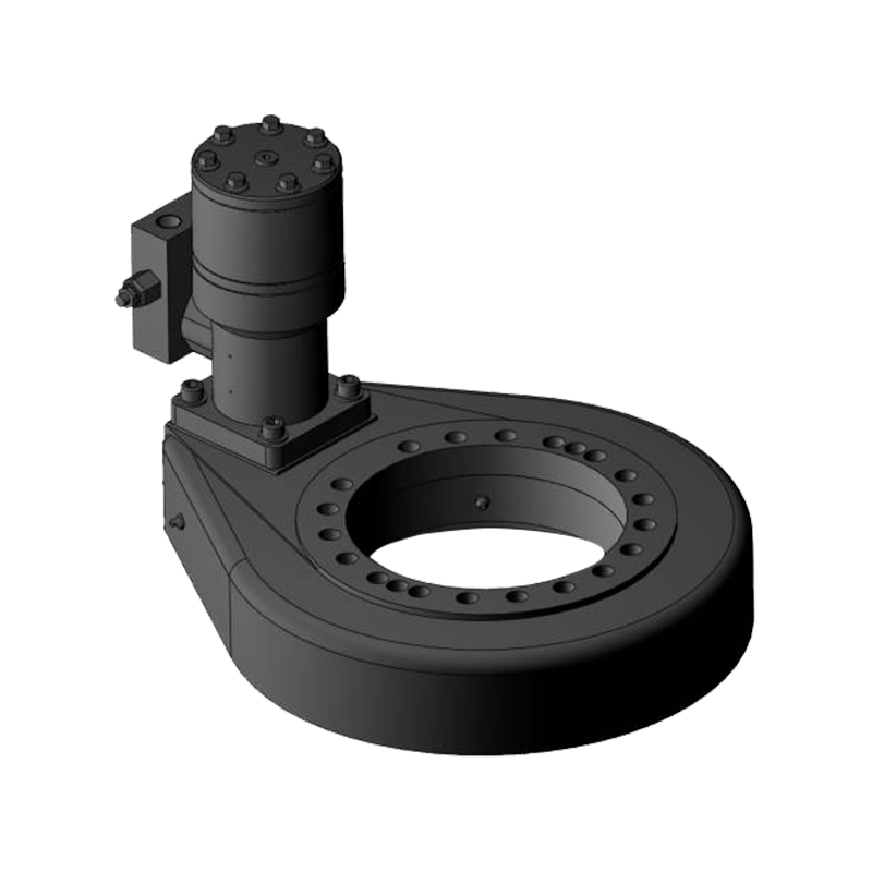
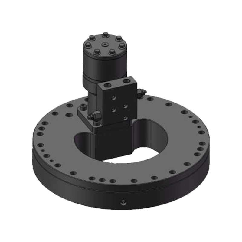
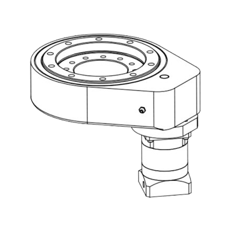
What Is a Triple Row Roller Slewing Ring Bearing?
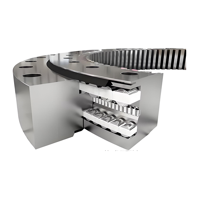
A triple row roller slewing ring bearing is a large-diameter, precision-engineered rotary bearing designed to simultaneously accommodate the full combination of axial loads, radial loads, and overturning moments that characterize the most demanding heavy-duty rotating machinery. Unlike single-row or double-row slewing bearings — which distribute these load types across a single or dual raceway arrangement with inherent capacity trade-offs — the triple row configuration dedicates separate, optimized rolling element rows to each primary load component. One row of cylindrical rollers handles axial loads acting downward, a second row handles axial loads acting upward or in reversal, and a third row of radial rollers manages the horizontal radial forces. This structural specialization allows each roller row to be precisely sized and positioned for its specific load function, delivering a combined load capacity that significantly exceeds what any single or double-row bearing of equivalent diameter can achieve.
The result is a bearing architecture that is uniquely suited to the most extreme slewing applications in industry — those involving very high combined loads, large overturning moments, shock loading, low rotational speeds, and demanding environmental conditions. Understanding when this architecture is the correct engineering specification — rather than an overspecified or underspecified choice — is essential for mechanical engineers, procurement specialists, and equipment designers working on heavy cranes, offshore platforms, industrial presses, and other capital equipment where bearing failure carries severe safety, operational, and economic consequences.
How the Triple Row Design Distributes Combined Loads
The defining engineering advantage of the triple row roller slewing ring bearing is its ability to manage complex, multi-directional load combinations without the capacity compromises inherent in simpler bearing geometries. To appreciate this, it is useful to examine how the load distribution works in practice across the three dedicated roller rows.
The upper axial roller row — typically the largest of the three, positioned between the upper faces of the inner and outer rings — carries the primary downward axial load generated by the weight of the rotating superstructure and its payload. In a harbor crane, for example, this is the combined weight of the crane boom, counterweight, hoist mechanism, and suspended load. Because this row is dedicated entirely to this function, its rollers can be sized to their maximum possible diameter within the bearing envelope, maximizing contact area and load distribution efficiency.
The lower axial roller row handles upward axial forces and the tensile component of overturning moments — the tendency of an offset load to lift one side of the bearing while pressing down on the other. In applications where the center of gravity of the rotating assembly is significantly offset from the bearing axis — which is the normal condition in virtually all crane and excavator applications — this overturning moment creates substantial reversing axial forces that a bearing without a dedicated lower axial row cannot effectively resist without risking raceway separation or roller skidding.
The radial roller row, positioned between the cylindrical inner and outer ring bore surfaces, manages horizontal forces acting perpendicular to the bearing axis. These forces arise from wind loading on the rotating structure, horizontal rope or chain tensions, machine vibration, and dynamic effects during slewing acceleration and deceleration. By isolating radial load management in its own dedicated roller row, the triple row design prevents the axial roller rows from being loaded obliquely — a condition that would reduce their effective load capacity and accelerate raceway wear.
Key Load Conditions That Signal the Need for a Triple Row Bearing
Not every slewing application requires the complexity and cost of a triple row roller bearing. The decision to specify this bearing type should be driven by a clear analysis of the load conditions the bearing must sustain. The following conditions, individually or in combination, indicate that a triple row roller slewing ring bearing is the appropriate engineering choice:
- Very high axial loads: When the primary axial load — the dead weight of the rotating assembly plus maximum payload — exceeds the capacity of single or double-row ball or roller slewing bearings of the available diameter range, the triple row configuration provides the additional axial capacity required within the same or similar outer envelope.
- Large overturning moments: Applications where the center of gravity of the rotating load is located far from the slewing axis generate large moment couples that create strongly opposing axial forces on opposite sides of the bearing. Triple row bearings with their dedicated upper and lower axial rows are specifically optimized for this load condition.
- Significant simultaneous radial loading: Where axial and radial loads are both large and act concurrently — as in offshore crane applications where wind and wave-induced lateral forces combine with heavy lifted loads — the dedicated radial row prevents cross-loading of the axial rows and maintains full capacity in all directions simultaneously.
- Shock and dynamic loading: Applications involving sudden load applications — crane hook engagements, impact from waves or seismic events, or rapid slewing starts and stops with heavy loads — generate peak forces significantly above the static design load. The higher static and dynamic capacity of the triple row design provides the safety margin required to survive these events without plastic deformation of the raceways.
- Low rotational speed with high load intensity: Triple row roller slewing bearings are optimized for the slow, heavily loaded rotational regime — typically less than 2 rpm — that characterizes most heavy crane, excavator, and press applications. Their line-contact roller geometry delivers superior load distribution compared to ball bearings under these conditions.
- Extended service life requirements: In applications where bearing replacement is extremely costly, disruptive, or operationally hazardous — such as offshore platforms, tunnel boring machines, or nuclear handling equipment — the higher static safety factors and more uniform load distribution of the triple row design translate directly into extended bearing life and reduced maintenance intervention frequency.
Primary Industries and Applications Where Triple Row Bearings Are Specified
Triple row roller slewing ring bearings are found at the heart of the most demanding rotating machinery across a defined set of industries where the combination of high loads, large diameters, and operational criticality consistently justifies their specification. Understanding these application contexts provides a practical reference framework for engineers evaluating whether this bearing type is appropriate for a new application.
Heavy Lifting Cranes — Port, Shipyard, and Offshore
Large harbor cranes, shipyard goliath cranes, offshore pedestal cranes, and floating crane vessels represent the application context for which the triple row roller slewing ring bearing is most thoroughly optimized. These machines operate with rated lift capacities of tens to hundreds of tonnes, boom radii of 30 to 100 meters or more, and must sustain full rated loads while rotating — often in the presence of wind loading and, for offshore units, vessel motion. The overturning moments generated at the slewing bearing by these operating conditions are among the largest in any industrial application, and the triple row bearing's dedicated moment-resistance architecture is the engineering response to this precise challenge. Bearing diameters for these applications typically range from 2 meters to over 6 meters, with multiple gear teeth machined directly into the outer ring for slewing drive engagement.
Large Hydraulic Excavators and Mining Shovels
In large hydraulic excavators — particularly those used in open-pit mining and major earthmoving projects with operating weights above 100 tonnes — the slewing bearing at the upper-to-lower structure interface must sustain enormous combined loads from the boom, stick, bucket, and payload while providing the rotational freedom for continuous 360° slewing. The dynamic nature of excavator operation — with rapid crowd, hoist, and swing cycles repeated thousands of times per shift — creates a highly variable load spectrum with significant peak-to-mean ratios. Triple row roller slewing bearings in mining excavator applications are typically specified with hardened raceways, high-pressure grease lubrication through integrated grease channels, and sealed configurations that exclude the rock dust, water, and abrasive contamination ubiquitous in mining environments.
Wind Turbine Pitch and Yaw Systems
Large wind turbines — particularly offshore units with rotor diameters exceeding 150 meters — use triple row roller slewing ring bearings in their yaw systems, which rotate the entire nacelle to track wind direction, and in some blade pitch adjustment systems. These applications impose very high combined loads from the aerodynamic thrust of the rotor, gravity loads from the nacelle mass, and significant cyclic loading from wind turbulence and rotor imbalance. The extremely long design life requirements of wind turbines — typically 20 to 25 years with minimal maintenance access — and the high cost of bearing replacement at hub height make the higher capacity and life of the triple row bearing particularly compelling in this sector.
Tunnel Boring Machines
The main bearing of a tunnel boring machine (TBM) — the large slewing bearing that supports the rotating cutter head against the reaction forces of rock cutting while providing the rotational axis for cutter head drive — is one of the most demanding slewing bearing applications in existence. Thrust forces from the cutting operation, combined with overburden and groundwater pressure acting on the cutter head face, generate very high axial loads. Radial forces from cutter head weight, eccentric rock formations, and cutter wear imbalance create substantial simultaneous radial loading. The complete inaccessibility of the main bearing during a TBM drive tunnel — which may last months or years — makes design conservatism and bearing reliability paramount, and triple row roller configurations are the standard specification for large-diameter TBM main bearings precisely because of these demands.
Comparing Slewing Bearing Types for Heavy-Duty Selection
The following table provides a direct comparison of the main slewing bearing types across the performance parameters most relevant to heavy-duty application selection, helping engineers identify the operating envelope where the triple row roller configuration delivers its greatest advantage:
| Parameter | Single Row Ball | Cross Roller | Double Row Ball | Triple Row Roller |
| Axial Load Capacity | Moderate | Good | Good | Excellent |
| Radial Load Capacity | Low | Moderate | Low–Moderate | Excellent |
| Moment Capacity | Low–Moderate | Good | Good | Excellent |
| Shock Load Tolerance | Low | Moderate | Moderate | High |
| Suitable Speed Range | Low to medium | Low to medium | Low to medium | Very low (<2 rpm) |
| Relative Cost | Low | Moderate | Moderate | High |
| Typical Diameter Range | 0.1 – 4.0 m | 0.1 – 3.0 m | 0.3 – 4.0 m | 1.0 – 8.0+ m |
Critical Design and Specification Considerations
Specifying a triple row roller slewing ring bearing for a heavy-duty application involves a series of engineering decisions beyond simply selecting the bearing with sufficient rated capacity. The interaction between the bearing, the supporting structures, the lubrication system, and the operating environment all significantly affect whether the bearing achieves its rated service life in practice.
Supporting Structure Stiffness
Triple row roller slewing bearings require stiff, flat, and precisely machined mounting surfaces on both the inner and outer ring contact faces. Deflection of the supporting structure under load causes the bearing rings to distort from their design geometry, introducing edge loading on the rollers and non-uniform stress distribution across the raceways that dramatically reduces bearing life. The mounting structure's bending stiffness should be sufficient to limit ring distortion under maximum combined loading to within the bearing manufacturer's specified mounting surface flatness tolerance — typically 0.05 to 0.15 mm across the full bolt circle diameter, depending on bearing size. Structural analysis of the supporting frame under all design load combinations should be an integral part of the bearing specification process, not an afterthought.
Gear Design and Drive System Integration
Most triple row roller slewing bearings for crane and heavy machinery applications are supplied with internal or external gear teeth machined into one of the rings, through which the slewing drive pinion engages to rotate the superstructure. Gear module selection, tooth profile, and gear quality grade must be consistent with the slewing torque requirements and the drive pinion specifications. Backlash between the slewing gear and drive pinion must be maintained within specified limits — too little backlash causes tooth interference and excessive wear, while too much allows impact loading during direction reversal that can damage both gear teeth and the bearing raceways. The slewing drive system — typically hydraulic or electric motor with planetary reduction — must also be sized to provide controlled, smooth starting torque that does not generate shock loads at the bearing during slewing initiation with maximum suspended loads.
Lubrication System Requirements
Effective lubrication of the three separate roller rows in a triple row bearing requires either a carefully designed manual grease replenishment system with multiple grease nipples positioned to reach each row, or an automatic centralized lubrication system that delivers measured grease quantities to each row at programmed intervals. Under-lubrication is the single most common cause of premature slewing bearing failure in heavy-duty applications — the combination of high contact stresses, low rotational speeds, and the tendency of grease to be pushed to the sides of the roller contact zone means that active grease replenishment must be maintained throughout the bearing's operating life, not just during initial commissioning. Grease selection should be based on the bearing manufacturer's recommendations for the specific operating temperature range, contamination environment, and load conditions of the application.
Condition Monitoring and Maintenance Best Practices
Given the high cost and operational criticality of the equipment in which triple row roller slewing bearings are installed, proactive condition monitoring and structured maintenance are essential to realizing the bearing's full design life and avoiding unplanned failures. The following practices represent the current best approach for maintaining these bearings in heavy-duty service:
- Periodic backlash measurement: Measuring the backlash between the slewing gear and drive pinion at defined intervals — typically every 500 to 1,000 operating hours — provides an indirect measure of raceway wear progression. Increasing backlash beyond the manufacturer's wear limit indicates raceway or roller wear that requires evaluation before the next major inspection interval.
- Bolt preload verification: Slewing bearing mounting bolts are subject to relaxation under cyclic loading and must be re-torqued to specified values at scheduled maintenance intervals. Loss of bolt preload reduces the stiffness of the bearing-structure interface and significantly accelerates raceway fatigue damage.
- Grease condition analysis: Collecting purged grease samples during replenishment and analyzing them for metal particle content, water contamination, and oxidation degradation provides early warning of abnormal wear or seal failure that would not otherwise be detectable until damage is advanced.
- Vibration and acoustic monitoring: Although the slow rotational speeds of most slewing bearing applications limit the effectiveness of conventional vibration analysis techniques, acoustic emission monitoring and structure-borne ultrasound measurement can detect early-stage raceway spalling and roller surface damage at speeds well below those accessible to standard vibration analysis methods.
- Visual inspection of seals and grease purge points: Regular visual inspection of the bearing seals for damage, displacement, or contamination ingress, combined with confirmation that grease is purging correctly from all designated purge points during replenishment, provides the first line of defense against the contamination and lubrication starvation failures that account for the majority of premature slewing bearing damage in field applications.
The triple row roller slewing ring bearing represents the apex of slewing bearing technology for heavy-duty combined load applications. Its specification is warranted whenever the load combination, required service life, and operational criticality of the application demand a bearing that provides not merely adequate capacity, but a genuine safety margin and life reserve that protects both the equipment and the people who operate it. For engineers willing to invest the analytical effort in thorough load analysis and mounting structure design, this bearing type delivers performance that no alternative configuration can match at the scale and load levels where it is most needed.


Jiangsu Manchen Transmission Technology Co., Ltd. excels in creating custom, reliable, and precise slewing bearings for diverse industries, continuously innovating to meet the highest standards and seeking collaborative opportunities. Reliable and steady slewing bearings supplier in China.
Product links
Contact Us
-
Address:No. 8, Nanqiu Road, Huangtu Town, Jiangyin City,China
-
Tel:+86-13646122221
-
Phone:+86-18796936198
-
WhatsApp:+86 18796936198
-
E-mail:hedy@slewingbearingcn.com
-
E-mail:ma@slewingbearingcn.com
-
E-mail:vena@slewingbearingcn.com
