 English
 русский
 Español
 عربى
عربى

News
 Home / News / Industry news / How Do You Choose the Right Horizontal Slewing Drive for Your Application?
 How Do You Choose the Right Horizontal Slewing Drive for Your Application?
 2026.05.13
 Industry news
Selecting the right horizontal slewing drive is one of those decisions that looks straightforward on the surface but quickly reveals layers of complexity when you dig into the application requirements. A poor selection doesn't just underperform — it fails prematurely, creates maintenance burdens, and in safety-critical systems can cause costly downtime or accidents. This guide walks through every meaningful selection variable, giving engineers and procurement specialists a practical framework for making the right call the first time.
Content
- 1 What a Horizontal Slewing Drive Actually Does
- 2 Load Analysis: The Non-Negotiable Starting Point
- 3 Torque Requirements and Motor Sizing
- 4 Key Selection Parameters Compared
- 5 Environmental and Duty Cycle Considerations
- 6 Mounting Configuration and Interface Geometry
- 7 Safety Factors and Service Life Expectations
- 8 Practical Checklist Before Finalizing Your Selection
What a Horizontal Slewing Drive Actually Does
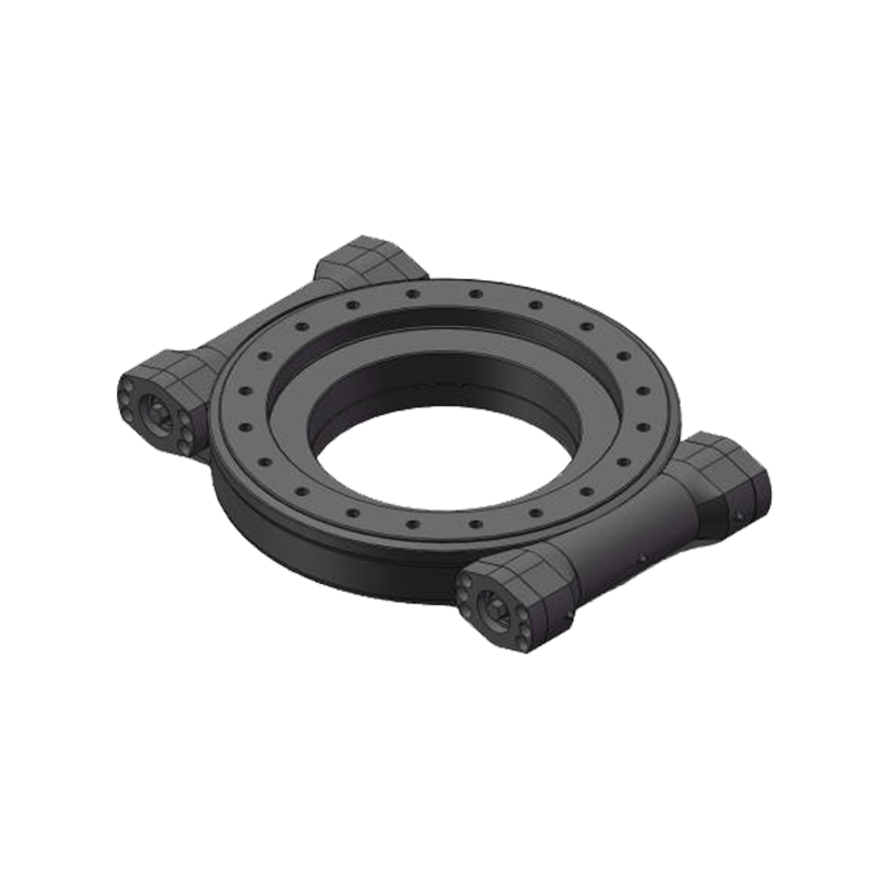
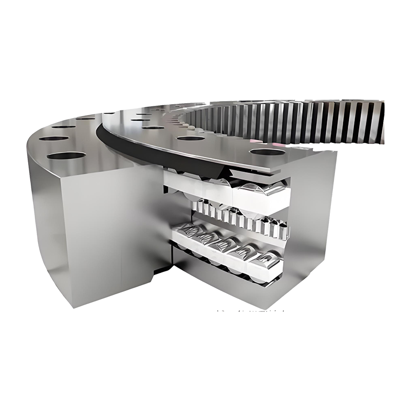
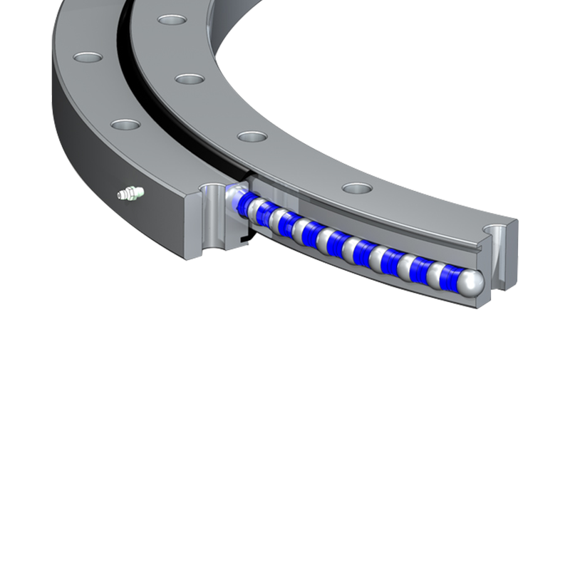
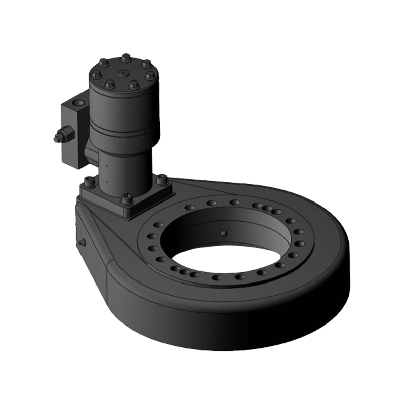
A horizontal slewing drive is a fully enclosed rotary actuator that combines a worm gear reduction mechanism with a slewing ring bearing in a single integrated housing. The slewing ring handles the radial, axial, and moment loads imposed by the rotating structure above, while the worm gear provides the mechanical advantage needed to drive that rotation with a relatively small motor input. "Horizontal" refers to the orientation of the drive's output axis — the rotation occurs around a vertical axis, making it the natural choice for applications where a structure must swing, pan, or continuously rotate in the horizontal plane.
Unlike standalone slewing rings paired with external gearboxes, an integrated horizontal slewing drive simplifies installation, improves sealing integrity, and reduces the engineering effort required to design the surrounding structure. This integration is precisely why they dominate applications like solar trackers, crane turntables, aerial work platforms, wind turbine yaw systems, and satellite antenna positioners — anywhere that compact, self-contained rotary actuation with high load capacity is required.
Load Analysis: The Non-Negotiable Starting Point
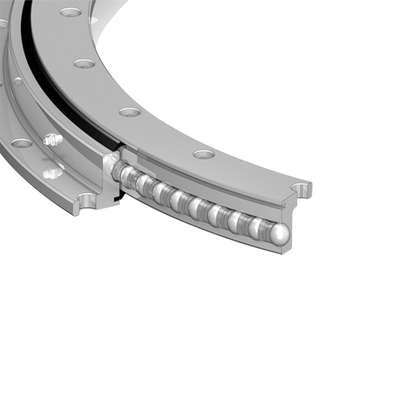
Every horizontal slewing drive selection begins with a complete load analysis. Skipping or approximating this step is the single most common source of premature failure. There are three categories of load that the drive must simultaneously handle, and all three must be quantified before any catalog comparison begins.
Axial Load
Axial load acts parallel to the drive's output axis — in a horizontal slewing drive, this is typically the dead weight of the rotating structure above. A solar panel array, a crane turntable superstructure, or an antenna assembly all impose their weight downward through the drive. This is the most straightforward load to calculate: it is essentially the total mass of everything rotating above the drive, multiplied by gravitational acceleration, and expressed in kilonewtons.
Radial Load
Radial load acts perpendicular to the output axis — horizontally, in the case of a horizontal slewing drive. Wind pressure on a large panel or antenna is the most common source of radial load in outdoor applications. Eccentric loading caused by an off-center center of gravity in the rotating assembly also contributes a radial component. Radial loads are often dynamic and directionally variable, which makes peak value estimation critical rather than average value calculation.
Overturning Moment
Overturning moment is the bending load that attempts to tilt the rotating structure relative to the drive housing. It is generated whenever the center of gravity of the rotating assembly is not directly above the drive's rotational centerline, or when horizontal forces (like wind) act at a height above the drive mounting plane. Overturning moment is expressed in kilonewton-meters and is frequently the most demanding load parameter — many drives that pass axial and radial load checks fail on overturning moment capacity.
Torque Requirements and Motor Sizing
Once loads are established, the required output torque must be calculated. This is the torque needed at the drive's output ring to overcome all resistive forces and accelerate the load to the required rotational speed within an acceptable time. The primary contributors to required torque are friction within the slewing ring bearing (which increases with axial load and overturning moment), aerodynamic drag on the rotating structure, and the inertial torque needed during acceleration phases.
Horizontal slewing drives are specified by their rated holding torque and rated working torque — these are not the same figure. Holding torque is the maximum static load the drive can sustain without rotation; working torque is the continuous torque available during operation. The worm gear's self-locking characteristic (present when the lead angle is below the friction angle, typically when the gear ratio exceeds approximately 20:1) means many horizontal slewing drives can hold their position under load without a separate brake — a feature that simplifies system design in applications like solar trackers where the drive must hold a panel angle against wind load without continuous motor energization.
Motor selection follows from the required input torque (output torque divided by the gear ratio, adjusted for drive efficiency) and the required input speed (output rotational speed multiplied by the gear ratio). Most horizontal slewing drives accept standard IEC or NEMA frame motors, and many are supplied motor-ready with a machined motor mounting flange.
Key Selection Parameters Compared
| Parameter | What to Determine | Common Range | Selection Risk if Underspecified |
| Axial Load Capacity | Total rotating mass × gravity | 5 kN – 2,000 kN | Bearing race deformation, seizure |
| Overturning Moment | Eccentric load × moment arm | 0.5 kNm – 500 kNm | Ring gear tooth failure, tilting |
| Working Torque | Friction + drag + inertia torque | 0.5 kNm – 200 kNm | Motor overload, worm gear wear |
| Output Speed | Required slew rate (°/min or rpm) | 0.01 – 10 rpm | Positioning error, thermal overrun |
| Gear Ratio | Self-locking need vs. efficiency | 20:1 – 100:1 | Back-driving, brake requirement |
Environmental and Duty Cycle Considerations
A drive that meets the mechanical load requirements on paper can still fail early if the environmental specification is wrong. Horizontal slewing drives are widely deployed outdoors, often in harsh conditions, and the housing, sealing, and surface treatment must be matched to the operating environment.
- IP Rating: For outdoor applications, a minimum of IP65 is generally required to exclude dust and water jets. Marine or coastal environments demand IP67 or higher, with stainless steel fasteners and additional corrosion protection on exposed surfaces. Confirm that the IP rating applies to the fully assembled drive including the motor interface — some drives are rated IP65 at the housing but have unprotected motor mounting faces that become ingress points.
- Temperature Range: Standard lubricants perform well between −20°C and +80°C. Applications in arctic environments, desert installations, or near industrial heat sources require specified low-temperature or high-temperature greases. Confirm the drive manufacturer's lubricant specification and the temperature range it covers before finalizing selection for extreme-climate deployments.
- Duty Cycle: Horizontal slewing drives in solar tracking applications typically operate intermittently — a brief movement every few minutes — placing low thermal demands on the worm gear assembly. Drives used in continuous-rotation applications such as antenna positioners or turntables face much higher thermal loads and require duty cycle ratings (expressed as operating time percentage) that match the application. Exceeding the duty cycle rating leads to lubricant degradation and accelerated worm gear wear.
- Corrosion Protection: Standard drives use zinc-phosphate primed and painted steel housings adequate for inland environments. Coastal and offshore installations require hot-dip galvanized housings, stainless steel output rings, or epoxy-coated surfaces depending on the corrosivity category of the site.
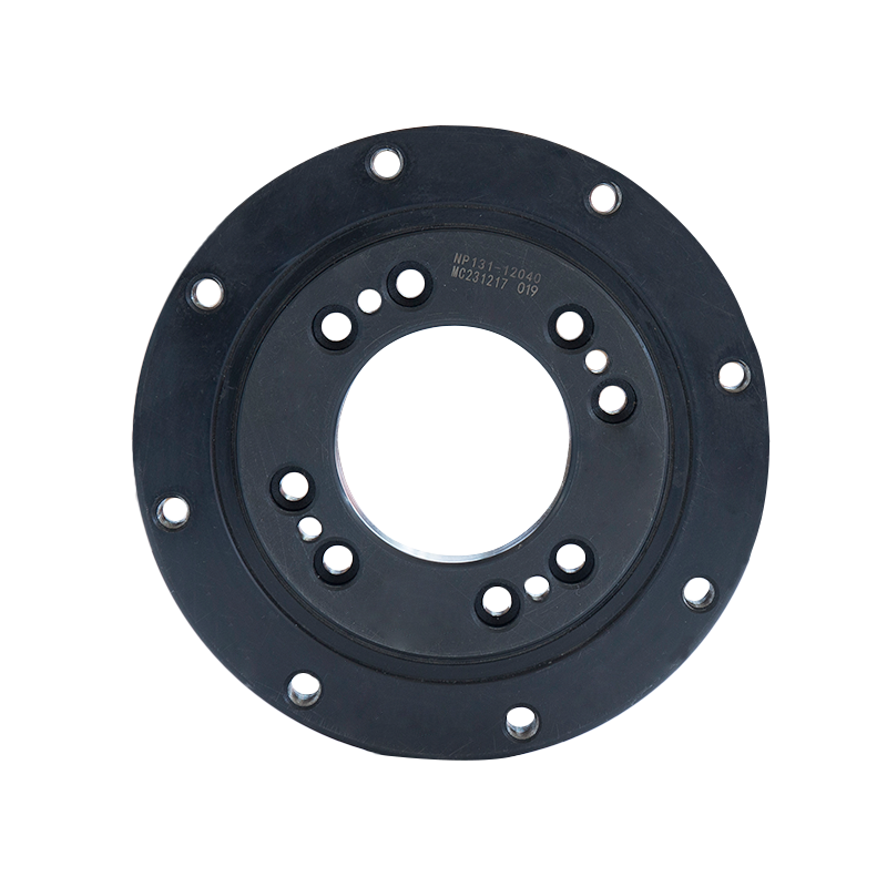
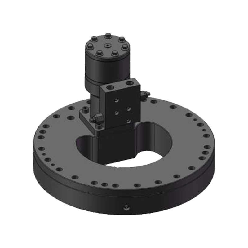
Mounting Configuration and Interface Geometry
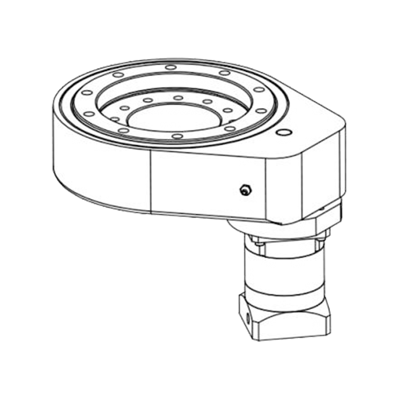
The physical integration of the slewing drive into the surrounding structure is a practical constraint that must be resolved during selection, not during installation. Horizontal slewing drives are available with different output ring configurations — external gear (teeth on the outside of the output ring), internal gear (teeth on the inside), and toothless (friction-driven or direct connection) — each suited to different kinematic arrangements. External gear output rings are most common and allow the worm shaft to be positioned outside the ring diameter, keeping the motor and gearbox accessible for maintenance. Internal gear configurations are used when the drive must be integrated into a compact rotating assembly.
Bolt circle dimensions on both the fixed housing and the rotating output ring must be verified against the mating structure. Many manufacturers offer customized bolt patterns, mounting flanges, and output shaft interfaces as standard options — specifying these at the ordering stage is far less expensive than machining adapters in the field. Verify also the through-hole diameter if cables, hydraulic lines, or pneumatic hoses must pass through the drive's center — not all horizontal slewing drives offer a center bore, and retrofitting this feature is not possible.
Safety Factors and Service Life Expectations
Published load ratings for horizontal slewing drives are typically based on static proof load or dynamic fatigue life calculations, and applying an appropriate safety factor above the calculated operating load is standard engineering practice. For most non-safety-critical applications, a safety factor of 1.5× to 2× on working torque and load capacity is appropriate. For applications where drive failure poses a risk to personnel — aerial work platforms, medical positioning equipment, or vehicle-mounted cranes — safety factors of 3× or higher may be specified, and third-party certification to relevant machinery safety standards (such as EN 13000 for cranes or ISO 11684 for agricultural equipment) should be confirmed with the drive manufacturer.
Expected service life should be discussed in terms of L10 bearing life (the number of operating hours at which 10% of a population of identical drives would be expected to show bearing fatigue failure) and worm gear surface fatigue life. For solar tracking applications, a 25-year design life is the industry norm; confirm that the manufacturer's L10 life calculation is based on the actual operating load profile of the application, not a generic reference condition.
Practical Checklist Before Finalizing Your Selection
- Confirm axial load, peak radial load, and maximum overturning moment under worst-case conditions (typically maximum wind speed combined with maximum eccentric load)
- Verify that the selected drive's rated working torque exceeds the calculated required output torque by the chosen safety factor
- Check the gear ratio for self-locking if passive position holding is required, or confirm the brake specification if it is not
- Confirm IP rating, temperature range, and corrosion protection match the installation environment
- Verify bolt circle dimensions, output ring configuration, and center bore requirements against the mating structure design
- Request L10 bearing life calculation based on actual application load profile, not catalog reference conditions
- Confirm motor interface compatibility — frame size, shaft diameter, and mounting flange standard (IEC or NEMA)
- Review lubrication specification and re-greasing interval against planned maintenance schedule
Horizontal slewing drive selection rewards methodical analysis. The drives themselves are robust, well-proven components — the failures that occur in the field are almost always traceable to an underspecified load parameter, a mismatched environmental rating, or an overlooked interface constraint. Work through each of the variables above systematically, engage the manufacturer's engineering support when application conditions are unusual, and the result will be a drive that performs reliably for the full intended service life of the system it powers.


Jiangsu Manchen Transmission Technology Co., Ltd. excels in creating custom, reliable, and precise slewing bearings for diverse industries, continuously innovating to meet the highest standards and seeking collaborative opportunities. Reliable and steady slewing bearings supplier in China.
Product links
Contact Us
-
Address:No. 8, Nanqiu Road, Huangtu Town, Jiangyin City,China
-
Tel:+86-13646122221
-
Phone:+86-18796936198
-
WhatsApp:+86 18796936198
-
E-mail:hedy@slewingbearingcn.com
-
E-mail:ma@slewingbearingcn.com
-
E-mail:vena@slewingbearingcn.com
